Communication between 3 or more devices using UART. EN/ES
There may be cases where we need our microcontroller to establish communication with two devices that handle serial communication, it may be between our device and two other microcontrollers that belong to some kind of sensor or simply a sensor that is connected to our device and we need to send its data to a computer.
In this article we will explore some situations in which a communication of this type may be required and how to solve the problem by creating a second serial port for our microcontroller by software, finally we will simulate communications between a microcontroller and two different devices through the serial port.
Pueden existir casos en los que necesitemos que nuestro microcontrolador establezca comunicación con dos dispositivos que manejan comunicación serial, puede ser entre nuestro dispositivo y otros dos microcontroladores que pertenezcan a algún tipo de sensor o simplemente un sensor que se conecta a nuestro dispositivo y debemos enviar sus datos a un ordenador.
En este artículo vamos a explorar algunas situaciones en las que una comunicación de este tipo puede ser requerida y como solucionar el problema creando por software un segundo puerto serial para nuestro microcontrolador, finalmente vamos a simular la comunicaciones entre un microcontrolador y dos dispositivos distintos mediante el puerto serial.

On the same board |
|---|
In some equipment the data processing and functions to be performed are too extensive to be carried out by a single microcontroller, it is then where the need arises to share tasks by adding other microcontrollers so that the device can perform its function efficiently.
If we consider some electronic devices such as computer cards, televisions, cell phones among others there will be a controller for sound, another to manage the screen, another for the camera and so each function within the device that demands high data processing and speed may have its own microcontroller dedicated to perform that task.
Even so all these microcontrollers must be integrated into the system sharing data between them and/or with a microprocessor or processor capable of giving instructions to all, this is generally called master.
En algunos equipos el procesamiento de datos y las funciones que se deben realizar son demasiado extensas para ser llevadas a cabo por un unico microcontrolador, es entonces donde surge la necesidad de compartir tareas añadiendo otros microcontroladores para que el dispositivo pueda cumplir su función de forma eficiente.
Si consideramos algunos aparatos electrónicos como tarjetas de ordenadores, televisores, celulares entre otros habrá un controlador para el sonido, otro para manejar la pantalla, otro para la camara y asi cada función dentro del dispositivo que demande un alto procesamiento de datos y velocidad quizás tenga su propio microcontrolador dedicado a realizar dicha tarea.
Aun así todos estos microcontroladores deben integrarse al sistema compartiendo datos entre ellos y/o con un microprocesador o procesador capaz de dar instrucciones a todos, este generalmente lo llamamos maestro

On different boards |
|---|
When the microcontrollers are in different devices, this could even be the communication between the different masters of each card, we assume that there are a number of engines in a plant and all are from the same manufacturer, each engine has a control card with a microcontroller capable of communicating to external devices.
A way of communication taking advantage that the devices are close is that all of them communicate with each other and one of them sends the important information to the computer located in the control room. This is in fact the way we are going to establish UART communication between two microcontrollers and a computer. And although we will only use two under the same principle we could add many more.
Cuando los microcontroladores están en dispositivos distintos, esta incluso podría ser la comunicación entre los distintos maestros de cada tarjeta, suponemos que existen una cantidad de motores en una planta y todos son del mismo fabricante, cada motor tiene una tarjeta de control con un microcontrolador capaz de comunicarse a dispositivos externos.
Un modo de comunicación aprovechando que las dispositivos están cerca es que todos ellos se comuniquen entre si y uno de ellos envie la informacion importante al ordenador ubicado en sala de control. Esta es de hecho la forma como vamos a establecer la comunicación UART entre dos microcontroladores y un ordenador. Y aunque solo usaremos dos bajo el mismo principio se pudiesen añadir muchos más.

Communication guidelines |
|---|
When there are only two people in a room the communication can flow without mentioning the name of the receiver, even if you do not look at him, whatever one says the other will interpret it as a communication to him.
But if there are 3 or more people the rules change, to communicate with any of them the sender must mention or identify him so that he understands that the message is for him.
Something similar happens with electronic devices, until now we only established communication between two devices, so any message sent by one of them was interpreted by the other as theirs. But now that more than two devices will be used it is necessary to establish an identification between them.
Suppose we have two microcontrollers, each of them controls an LED and we will use a computer to send instructions to them. Previously we only sent one message, but now it is not enough to send only one message to turn on an LED, we must say in the message for which of the two microcontrollers is the message.
Cuando solo están dos personas en una sala la comunicación puede fluir sin que haga falta mencionar el nombre del receptor, incluso si no le mira cualquier cosa que diga uno el otro lo interpretará como una comunicación hacia el.
Pero si hay 3 o más personas las reglas cambian, para comunicarse con alguno de ellos el emisor deberá mencionarlo o identificarlo para que de esta forma entiende que el mensaje es para el.
Algo similar ocurre con los dispositivos electrónicos, hasta ahora solo establecíamos comunicación entre dos dispositivos, así que cualquier mensaje que enviaba uno el otro lo interpretaba como suyo. Pero ahora que se usaran más de dos dispositivos es necesario establecer una identificación entre ellos.
Supongamos que tenemos dos microcontroladores, cada uno de ellos controla un LED y nosotros usaremos un ordenador para enviarles instrucciones. Anteriormente solo enviamos un mensaje, pero ahora no solo basta con enviar un mensaje para encender un LED, debemos decir en el mensaje para cual de los dos microcontroladores es el mensaje.

When a message is sent to a microcontroller that is not the closest to the computer, all those before it will receive the message, interpret who the recipient is and pass it to the next microcontroller until it reaches its destination.
We will be able to notice that always at the end of the loop there will be a microcontroller that only communicates with a device, for that case the identification can be obviated since it is only possible to receive messages by a single channel.
Cuando se envía un mensaje a un microcontrolador que no es el más próximo al ordenador todos los que estén antes que él recibirán el mensaje, interpretaran quien es el destinatario y lo pasaran al microcontrolador siguiente hasta que llegue a su destino.
Podremos notar que siempre al final del lazo habrá un microcontrolador que solo se comunicara con un dispositivo, para ese caso se puede obviar la identificación ya que solo es posible que reciba mensajes por un solo canal.
Programming U1 |
|---|
We have 3 devices, at one end is a computer, in the center is our microcontroller that will communicate with the computer and with a second microcontroller at the other end. We will use the microcontroller in the center (U1) to illustrate how to establish communication between a microcontroller and two devices simultaneously, so the programming of U1 will serve for all microcontrollers that are not at one end of the loop (those that need to communicate with two devices).
To give identity to a device we use STREAM=ID in the RS232 configuration line, replace ID by the name we want for the device. To enable the second serial port by software we write another similar line but change the Pins to use. That way our configuration lines will look like the following code.
Tenemos 3 dispositivos, en un extremo está un ordenador, en el centro nuestro microcontrolador que se comunicara con el ordenador y con un segundo microcontrolador en el otro extremo. Usaremos el microcontrolador del centro (U1) para ilustrar como se establece la comunicación entre un microcontrolador y dos dispositivos de forma simultánea por lo cual la programación de U1 servirá para todos los microcontroladores que no estén en un extremo del lazo (los que necesiten comunicarse con dos dispositivos).
Para darle identidad a un dispositivo usamos STREAM=ID en la línea de configuración RS232, reemplazamos ID por el nombre que deseamos para el dispositivo. Para habilitar el segundo puerto serial por software escribimos otra línea parecida pero cambiamos los Pines a usar. De esa forma nuestras líneas de configuración quedaran con el siguiente código.
#include <16f877a.h>

#device PASS_STRINGS = IN_RAM

#fuses HS,NOWDT,NOPROTECT,NOPUT,NOLVP,BROWNOUT

#use delay(clock=20M)

#use RS232(BAUD=9600, BITS=8, PARITY=N, XMIT=PIN_C6,
RCV=PIN_C7, STREAM=PIC)

#use RS232(BAUD=9600, BITS=8, PARITY=N, XMIT=PIN_C4,
RCV=PIN_C5, STREAM=PC)

#use standard_io(D)

#include <stdio.h

#include <string.h

#define led PIN_D1
We define the PIC serial port to communicate with the second microcontroller and the PC port on pins C4 and C5 to communicate with the computer.
The idea is that in both microcontroller U1 and U2 there is a LED that we can control from the computer, in this case we define the LED connection in pin D1.
We define the string variable to handle the received data and in the main program we start by sending my usual welcome message. 😊
Definimos el puerto serial PIC para comunicarnos con el segundo microcontrolador y el puerto PC en los pines C4 yC5 para comunicarnos con el ordenador.
La idea es que tanto en el microcontrolador U1 como en el U2 existe un led que podemos controlar desde el ordenador, en este caso definimos la conexión del LED en el PIN D1.
Definimos la variable string para manejar los datos recibidos y en el programa principal iniciamos enviando mi acostumbrado mensaje de bienvenida. 😊
char string[20];

void main()

{

   output_low(led);

   delay_ms(400);

   fprintf(PC,"WELCOME TO MY BLOG\r\n");

   delay_ms(400);

   fprintf(PC,"Communication between 3 or more devices using UART. EN/ES\r\n");

   delay_ms(400);

   fprintf(PC,"@electronico - HIVE\r\n");

   delay_ms(400);

   fprintf(PC,"ORIGINAL CONTENT\r\n");

   delay_ms(400);
It is important to highlight that for this case we cannot transmit data with the printf() function but we use fprintf() which allows us to define to whom the data will be directed, for this the format is fprintf(ID, "DATO"), which makes us understand that the previous message was transmitted by the port connected to the computer, that is, it will be displayed on the computer.
Now kbhit (which is used to detect when a data has been received) must also have the parameter ID, this way we are defining which device has sent the data and we can write the actions to execute accordingly, usually we do it with the conditional if.
When we want to verify data from the computer we use if(kbhit(PC) > 0) and when we want to verify data from the second microcontroller U2 we use if(kbhit(PIC) > 0), and then we set the actions to be executed.
In the case of U1 we verify if the string is intended to be operated by U1, for this the string must be u1_led_on to turn on the led of U1 and u1_led_off to turn it off. In case the string does not match with any of these two the microcontroller assumes that any other different string is not intended to be operated by it and transmits it to the next microcontroller U2.
Every time U1 receives a data it will return that same data to the sender, even if it is not intended to be executed by U1, this is just a way to check that the communication is being established. The way to receive a data is with the function fgets(variable, ID); where variable is the name of the vector in which we will store the data and ID is the source from where the data will be obtained. All this is reflected in the following code:
Es importante resaltar que para este caso no se puede transmitir datos con la función printf() sino que usamos fprintf() que nos permite definir hacia quien irá dirigido el dato, para esto el formato es fprintf(ID,"DATO"), lo que nos hace entender que el mensaje anterior fue transmitido por el puerto conectado al ordenador, es decir, se mostrará en el ordenador.
Ahora kbhit (que se usa para detectar cuando se ha recibido un dato) también debe tener el parámetro ID, de esta forma estamos definiendo cuál dispositivo ha enviado el dato y podemos escribir las acciones a ejecutar en consecuencia, generalmente lo hacemos con el condicional if.
Cuando queremos verificar datos desde el ordenador usamos if(kbhit(PC) > 0) y cuando queremos verificar datos desde el segundo microcontrolador U2 usamos if(kbhit(PIC) > 0), y a continuación establecemos las acciones a ejecutar.
En el caso de U1 verificamos si la cadena de caracteres está destinada a ser operada por U1, para ello la cadena debe ser u1_led_on para encender el led de U1 y u1_led_off para apagarlo. En caso de no coincidir la cadena con ninguna de estas dos el microcontrolador asume que cualquier otra cadena distinta no está destinada a ser operada por el y la transmite al siguiente microcontrolador U2.
Cada vez que U1 reciba un dato regresará ese mismo dato al remitente, incluso si no está destinado a ser ejecutado por U1, está solo es una forma de comprobar que la comunicación esta siendo establecida. La forma de recibir un dato es con la función fgets(variable, ID); donde variable es el nombre del vector en el cual almacenaremos el dato e ID es la fuente desde donde se obtendrá el dato. Todo lo dicho se refleja en el siguiente código:
while(true)

  {

      if(kbhit(PC) > 0)

      {

         fgets(string, PC);

         fprintf(PC,"Received data: [%s]\r\n\r\n", &string);

         if(strstr(string, "u1_led_on"))

         {

            output_high(led);

            fprintf(PC,"U1 LED: ON\r\n\r\n");

         }

         else if(strstr(string, "u1_led_off"))

         {

            output_low(led);

            fprintf(PC,"U1 LED: OFF\r\n\r\n");

         }

         else

         {

         fprintf(PIC,"%s\r\n", &string);

         }
fprintf(PIC,"%s "r", &string); is the line we are using to send to the next microcontroller all the data that are not usable by the first one, if there were more microcontrollers in the loop (U3, U4,... Un) the next microcontroller would have the same line to pass unusable data to the next one and so on. For the purposes of unusable data the microcontroller would only fulfill the function of "repeater".
As U2 does not exert actions on U1 but only the computer, the function of U1 in front of U2 is that of a repeater, that is to say, everything that U1 receives from U2 will be transmitted to the computer, which we achieve with the following code.
fprintf(PIC,"%s\r\n", &string); es la línea que estamos usando para enviar al siguiente microcontrolador todos los datos que no sean usables por el primero, si existiesen más microcontroladores en el lazo (U3, U4,... Un) el siguiente microcontrolador tendría la misma línea para pasar datos no usables al siguiente y así sucesivamente. Para efectos de los datos no usables el microcontrolador solo cumpliria la funcion de "repetidor".
Como U2 no ejerce acciones en U1 sino solo el ordenador, la función de U1 frente a U2 es la de repetidor, es decir, todo lo que U1 reciba desde U2 lo transmitirá al ordenador lo cual logramos con el siguiente código.
 if(kbhit(PIC) > 0)

        {

          fgets(string, PIC);

          fprintf(PC,"%s\r\n", &string);

        }
Programming U2 |
|---|
In this case U2 represents the device at the end, what this means is that U2 is only connected to one device so we can use the knowledge and functions seen in past articles to set up our control logic. First we define the configuration lines.
En este caso U2 representa al dispositivo en el extremo, lo que esto significa es que U2 solo esta conectado a un dispositivo por lo cual podemos usar los conocimientos y funciones vistas en artículos pasados para establecer nuestra lógica de control. En primer lugar definimos las líneas de configuración.
#include <16f877a.h>

#device PASS_STRINGS = IN_RAM

#fuses HS,NOWDT,NOPROTECT,NOPUT,NOLVP,BROWNOUT

#use delay(clock=20M)

#use RS232(BAUD=9600, BITS=8, PARITY=N, XMIT=PIN_C6, RCV=PIN_C7)

#include <get_string.c

#use standard_io(D)
We will use the string variable to handle the received data and in the PIN D1 we will connect the LED of U2, to turn on the led the string u2_led_on must be received and to turn it off u2_led_off, as this is a device at the end we will not use ID, therefore the functions that do not require the ID parameter can be used.
Usaremos la variable string para manejar los datos recibidos y en el PIN D1 conectaremos el LED de U2, para encender el led se debe recibir la cadena u2_led_on y para apagarlo u2_led_off, como este es un dispositivo en el extremo no usaremos ID, por lo tanto las funciones que no requieren el parámetro ID pueden ser usadas.
char string[20];

void main()

{

   output_low(PIN_D1);

   while(true)

   {

      if(kbhit() > 0)

      {

        read_string(string, 20);

        if(!strcmp(string, "u2_led_on"))

            {

             output_high(PIN_D1);

             printf("U2 LED: ON\r\n\r");

            }

        if(!strcmp(string, "u2_led_off"))

            {

             output_low(PIN_D1);

             printf("U2 LED: OFF\r\n\r");

            }

      }

   }
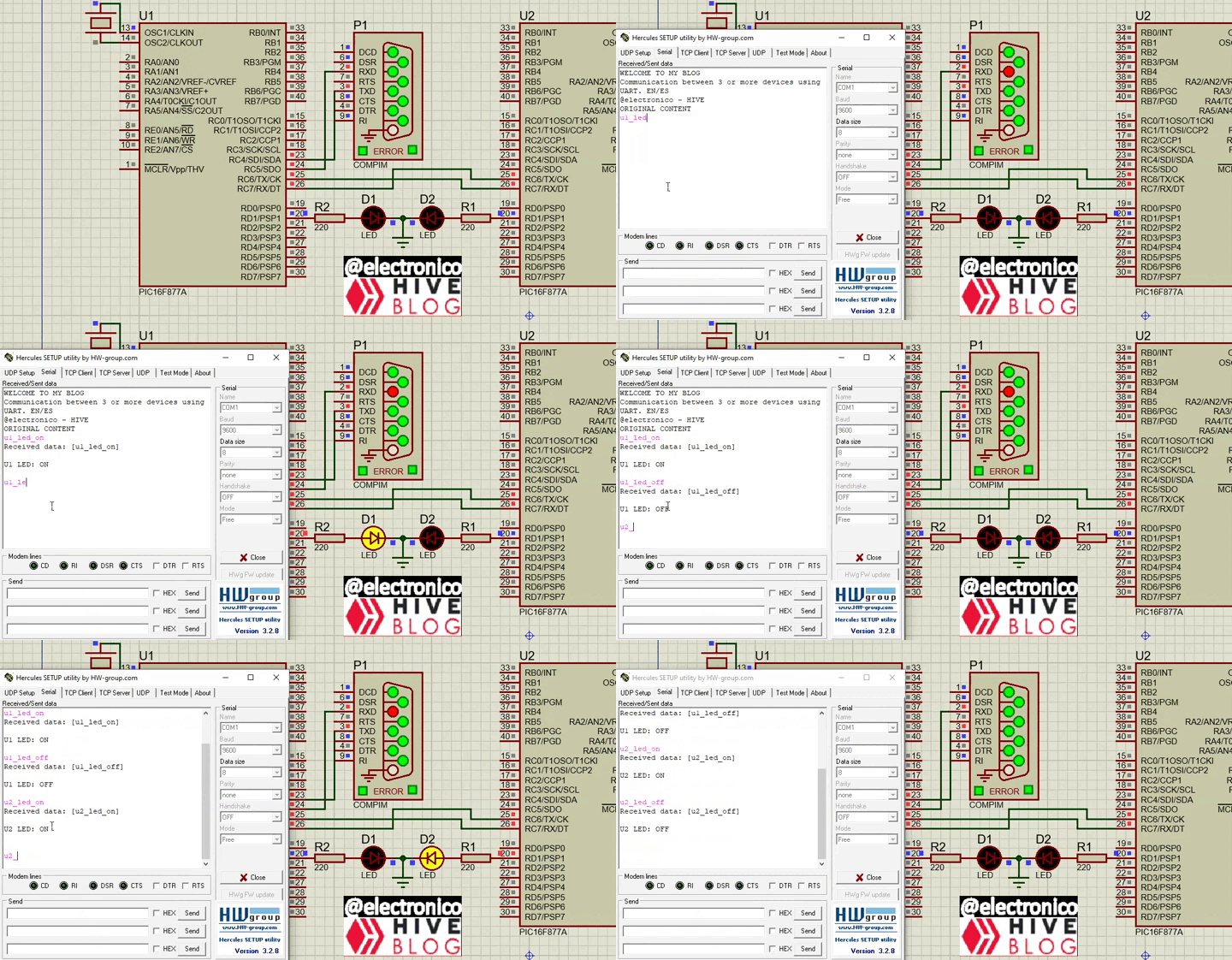
It is important to note that when an action is executed in the LED of both U1 and U2 a message is returned confirming that the action was executed, in the case of U2 the message is transmitted to U1 and this in turn transmits it to the computer. Thus, when an applicable command is sent, two confirmation messages are received, the first one is always sent by U1 simply repeating the string that was received to confirm that the communication was correct.
The second message will be sent by the microcontroller that executed the action to confirm that the instruction was carried out.
Es importante resaltar que cuando se ejecuta una acción en el LED tanto de U1 como de U2 se regresa un mensaje confirmando que la acción fue ejecutada, en el caso de U2 el mensaje es transmitido hacia U1 y este a su vez lo transmite al ordenador. Así, cuando se envía un comando aplicable se reciben dos mensajes de confirmación, el primero siempre lo enviará U1 simplemente repitiendo la cadena que se recibió para confirmar que la comunicación fue correcta.
El segundo mensaje lo enviara el microcontrolador que ejecuto la accion para confirmar que se llevó a cabo la sentencia.
SIMULATION |
|---|
For our simulation we will use the Hercules program to send the data from the computer, we will send the instructions to turn on the LED in U1 and then turn it off, then we will do the same for U2, if the sentences are executed correctly we will be controlling two microcontrollers from the same computer and the knowledge acquired could allow us to connect more microcontrollers if necessary.
Para nuestra simulación usaremos el programa Hércules para enviar los datos desde el ordenador, enviaremos las instrucciones de encender el LED en U1 y luego apagarlo, posteriormente haremos lo mismo para U2, si se ejecutan las sentencias correctamente estaremos controlando dos microcontroladores desde un mismo ordenador y los conocimientos adquiridos podrían permitirnos conectar mas microcontroladores si fuese necesario.


¡Enhorabuena!
✅ Has hecho un buen trabajo, por lo cual tu publicación ha sido valorada y ha recibido el apoyo de parte de CHESS BROTHERS ♔ 💪
♟ Te invitamos a usar nuestra etiqueta #chessbrothers y a que aprendas más sobre nosotros.
♟♟ También puedes contactarnos en nuestro servidor de Discord y promocionar allí tus publicaciones.
♟♟♟ Considera unirte a nuestro trail de curación para que trabajemos en equipo y recibas recompensas automáticamente.
♞♟ Echa un vistazo a nuestra cuenta @chessbrotherspro para que te informes sobre el proceso de curación llevado a diario por nuestro equipo.
🥇 Si quieres obtener ganancias con tu delegacion de HP y apoyar a nuestro proyecto, te invitamos a unirte al plan Master Investor. Aquí puedes aprender cómo hacerlo.
Cordialmente
El equipo de CHESS BROTHERS
Thanks for your contribution to the STEMsocial community. Feel free to join us on discord to get to know the rest of us!
Please consider delegating to the @stemsocial account (85% of the curation rewards are returned).
You may also include @stemsocial as a beneficiary of the rewards of this post to get a stronger support.