Component electronics: Operational amplifier (Open loop) EN/ES
In previous articles we described some electronic components classifying them as passive components and active components comprising Semiconductors, for the semiconductor group we described the diode and transistors.
The rest of the semiconductor components are made of these two, that is, we could use transistors to develop the same operations that any integrated semiconductor circuit performs, the disadvantage is that for these operations we would have to use circuits with hundreds, thousands and millions of transistors, which would make their physical implementation with independent transistors impossible.
Fortunately, technological advances allow the integration of these circuits with thousands and millions of transistors in a single component called Integrated Circuit, as expected a single integrated circuit will not serve for all applications and hence many have been manufactured with different utilities, some even for specific purposes.
Of all the integrated circuits that exist I would like to familiarize us with those that can be used in a greater number of applications and of all of them I dare to say that hardly any has greater utility than an Operational Amplifier, that is why today we will learn about this component.
En artículos anteriores describimos algunos componentes electrónicos clasificando estos como componentes pasivos y los componentes activos que comprenden a los Semiconductores, para el grupo de los semiconductores describimos el diodo y los transistores.
De estos dos están hechos el resto de los componentes semiconductores, es decir, podríamos usar transistores para desarrollar las mismas operaciones que realice cualquier circuito semiconductor integrado, la desventaja es que para estas operaciones tendríamos que usar circuitos con cientos, miles y millones de transistores lo que haría imposible su implementación física con transistores independientes.
Afortunadamente los avances tecnológicos permiten integrar estos circuitos con miles y millones de transistores en un solo componente bastante reducido llamado Circuito Integrado, como es de esperar un solo circuito integrado no servirá para todas las aplicaciones y de ahí que se hayan fabricado muchísimos con diferentes utilidades, algunos incluso con propósitos específicos.
De todos los circuitos integrados que existen me gustaría que nos familiaricemos con aquellos que pueden ser usados en un mayor número de aplicaciones y de todos ellos me atrevo a decir que difícilmente alguno tenga mayor utilidad que un Amplificador Operacional, es por eso que hoy aprenderemos sobre este componente.
Operational Amplifier Terminals |
|---|
An operational amplifier is an electronic component that can be used to design circuits with a wide variety of applications, such as performing mathematical operations, filtering frequencies, amplifying signals, sensors, actuators and many others.
There are voltage, current and power operational amplifiers, among others. The one presented below is a voltage amplifier and in the following image we will see its symbology in which we will take into account the terminals and then explain the function of each one.
Un amplificador operacional es un componente electrónico con el que se pueden diseñar circuitos con una enorme variedad de aplicaciones, como realizar operaciones matemáticas, filtrar frecuencias, amplificar señales, sensores, actuadores y muchos otros.
Existen amplificadores operacionales de Tensión, de Corriente, de potencia entre otros. El que presentamos a continuación es un amplificador de Tensión y en la siguiente imagen veremos su simbología en la cual tomaremos en cuenta los terminales para posteriormente explicar la función de cada uno.

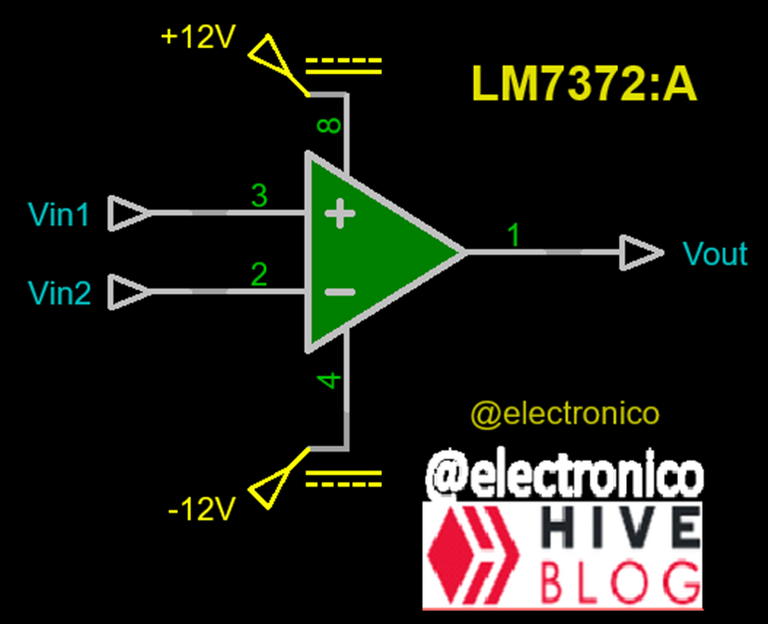
In the figure we can see the symbol of an operational amplifier with the most important pins layout (that's why you don't see the 5, 6 and 7), this illustration corresponds to the LM7372 but we can use it as a reference to understand the pins according to their position because for other models the pin number may change but if it is in the same position it will continue to do the same function.
An operational amplifier is formed by two input pins which in this case are pin 3 that goes to (+) and is called "non-inverting input", its name is because if the output only depends on that input then the polarity of the output will be the same as the input.
On the other hand, pin 2 with the sign (-) is called "inverting input" because if the output only depends on that input then it will have an opposite polarity. Pin 1 is the output.
On the sides we have pins 8 and 4 and correspond to the voltages with which the operational amplifier must be fed, this power supply can be symmetrical (+v at one end and -v at the other, both voltages with the same magnitude) or asymmetrical (different values on both pins but with the correct polarity because one must be fed with a voltage greater than or equal to zero and the other with a voltage less than or equal to zero).
En la figura podemos ver el símbolo de un amplificador operacional con la disposición de pines más importantes (por eso no ves el 5, 6 y 7), esta ilustración corresponde al LM7372 pero podemos usarlo como referencia para entender los pines según su posición ya que para otros modelos el número del pin puede cambiar pero si está en la misma posición seguirá haciendo la misma función.
Un Amplificador operacional esta formado por dos pines de entradas que para este caso son el pin 3 que llega al (+) y se llama "entrada no inversora", su nombre se debe a que si la salida solo depende de esa entrada entonces la polaridad de la salida será la misma que la de la entrada.
En contraparte el pin 2 con el signo (-) se llama entrada inversora porque si la salida solo depende de esa entrada entonces tendrá una polaridad opuesta. El pin 1 es la salida.
En los laterales tenemos los pines 8 y 4 y corresponden a las tensiones con las que debe alimentarse el amplificador operacional, esta alimentación puede ser simétrica (+v en un extremo y -v en el otro, ambas tensiones con la misma magnitud) o asimétrica (valores distintos en ambos pines pero con la polaridad correcta ya que uno debe ser alimentado con un voltaje mayor o igual a cero y el otro con un voltaje menor o igual a cero).
Operating principles |
|---|
An operational amplifier has two fundamental ways of operating, in open loop which is when part of the output voltage is not injected at the input terminals and closed loop which is when it is done by means of a passive feedback component such as a resistor, a capacitor or a coil. Then, depending on whether it is used in open loop or closed loop, it will present other forms and different configurations according to the utility that you want to give it.
For the purposes of this article we will begin by trying to understand its operation in open loop, as it is an amplifier we have to assume that it will have a gain that is multiplied by an input value to produce an amplified output.
Immediately we can notice that there is not one input but 2 and this should lead us to the following question: Which of the inputs will be amplified at the output? Actually neither of the two but the difference between them, i.e. Vout=(Vin1-Vin2)B where B represents the gain of the amplifier.
If the result of this difference is positive the output will be a positive voltage, if it is negative so will be the output. When we use the Operational Amplifier in open loop the gain is so high that a voltage in the order of microvolts can cause a saturated output, this makes it useless to amplify signals, however we can take advantage of this principle to give another type of utility.
Un amplificador operacional tiene dos formas fundamentales de operar, en lazo abierto que es cuando no se inyecta parte del voltaje de salida en los terminales de entrada y lazo cerrado que es cuando si se hace mediante algún componente pasivo de realimentación como una resistencia, un capacitor o una bobina. Luego según se use en lazo abierto o lazo cerrado presentará otras formas y configuraciones distintas según la utilidad que se le desee dar.
Para efectos de este artículo iniciaremos intentando comprender su operación en lazo abierto, como es un amplificador tenemos que suponer que tendrá una ganancia que se multiplique por un valor de entrada para producir una salida amplificada.
De inmediato podremos notar que no existe una entrada sino 2 y esto nos debe llevar a la siguiente pregunta ¿Cuál de las entradas será amplificada a la salida? realmente ninguna de las dos sino la diferencia entre ambas, es decir Vout=(Vin1-Vin2)B donde B representa la ganancia del amplificador.
Si el resultado de dicha diferencia es positivo la salida será un voltaje positivo, si es negativo también lo será la salida. Cuando usamos el Amplificador Operacional en lazo abierto la ganancia es tan alta que un voltaje en el orden de los microvoltios puede provocar una salida saturada, esto lo hace inservible para amplificar señales, sin embargo nosotros podemos aprovechar ese principio para darle otro tipo de utilidad.
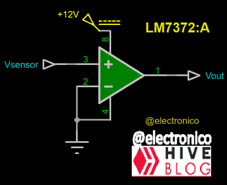
Some transducers (sensing element that converts one type of energy to another with proportional magnitudes) can only generate small amounts of voltage in the order of millivolts, if we connect these values to the non-inverting input of an operational amplifier like the one in the figure, we will have an output of 12V to the existence of any voltage value that is greater than 0V.
In this case we made the inverting input to be zero and that will be the value with which the non-inverting input is being compared at all times, when this input is less than or equal to zero the output will be zero because we do not feed the operational amplifier with negative voltages, when the value of the non-inverting input is greater than zero we will have an output of 12V that can be used to generate the corresponding actions.
Algunos transductores (elemento sensor que convierte un tipo de energía a otro con magnitudes proporcionales) solo pueden generar pequeñas cantidades de tensión del orden de los milivoltios, si conectamos esos valores a la entrada no inversora de un amplificador operacional como el de la figura, tendremos una salida de 12V ante la existencia de cualquier valor de tensión que sea mayor a 0V.
En este caso hicimos que la entrada inversora sea cero y ese será el valor con el que se esté comparando en todo momento la entrada no inversora, cuando esta entrada sea menor o igual que cero la salida será cero porque no alimentamos el amplificador operacional con tensiones negativas, cuando el valor de la entrada no inversora sea mayor que cero tendremos una salida de 12V que puede ser utilizada para generar las acciones que correspondan.
Simulation |
|---|
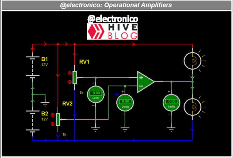
To illustrate it better let's simulate the circuit used as cover image in this article (the first image), what we have is an operational amplifier fed symmetrically (by two voltage sources of the same value), it means that we have positive power supply and negative power supply which implies that the output can also have these values with the same polarities.
In the inverting and non-inverting inputs we have potentiometers that generate a voltage division for each input, by means of these we can make that any of the two inputs is greater and produce a positive or negative output according to the case.
When the output is positive the voltage in the upper lamp is zero because it will have 12V from the source at one end and 12V from the amplifier output at the other, as the voltage is the same at both ends no current will flow through the lamp, but the other lamp should light because it will have at one end the positive voltage of the output and the other the negative voltage of the source.
The same thing will happen if the output is negative, the upper lamp will light but the lower one will not because it will have two negative voltages of equal magnitude at its ends.
If we equalize the two input voltages then the output will be 0V and as the operational amplifier has a high input impedance then both lamps will light.
Para ilustrarlo mejor vamos a simular el circuito usado como imagen de portada en este artículo (la primera imagen), lo que tenemos es un amplificador operacional alimentado de forma simétrica (por dos fuentes de tensión del mismo valor), significa que tenemos alimentación positiva y alimentación negativa lo que implica que la salida puede tener también estos valores con las mismas polaridades.
En las entradas inversora y no inversora tenemos potenciómetros que generan una división de tensión para cada entrada, mediante estos podemos hacer que cualquiera de las dos entradas sea mayor y producir una salida positiva o negativa según sea el caso.
Cuando la salida es positiva el voltaje en la lámpara superior es cero porque tendrá 12V de la fuente en un extremo y 12V de la salida del amplificador en el otro, como el voltaje es el mismo en sus dos extremos no circulará corriente por dicha lámpara, pero la otra lámpara deberá encender porque tendrá en un extremo el voltaje positivo de la salida y en el otro el negativo de la fuente.
Ocurrirá lo mismo si la salida es negativa, encenderá la lámpara superior pero la inferior no lo hará porque tendrá dos tensiones negativas de igual magnitud en sus extremos.
Si igualamos las dos tensiones de entrada entonces la salida será 0V y como el amplificador operacional tiene una alta impedancia de entrada entonces las dos lámparas encenderán.


Congratulations @electronico! You have completed the following achievement on the Hive blockchain And have been rewarded with New badge(s)
Your next payout target is 1000 HP.
The unit is Hive Power equivalent because post and comment rewards can be split into HP and HBD
You can view your badges on your board and compare yourself to others in the Ranking
If you no longer want to receive notifications, reply to this comment with the word
STOPTo support your work, I also upvoted your post!
Check out our last posts:
And let's go for more my friend, I am anxious to become a whale that can give a big vote to others, including you my friend.

Looking forward to you becoming a whale @electronico 🐳😅
Nice and clear explanation ! Thank you!
I'm glad you find it useful
Yay! 🤗
Your content has been boosted with Ecency Points, by @electronico.
Use Ecency daily to boost your growth on platform!
Support Ecency
Vote for new Proposal
Delegate HP and earn more
Thanks for your contribution to the STEMsocial community. Feel free to join us on discord to get to know the rest of us!
Please consider delegating to the @stemsocial account (85% of the curation rewards are returned).
You may also include @stemsocial as a beneficiary of the rewards of this post to get a stronger support.