Introduction to DC motor control EN/ES
I am sure that when you hear the word engine all my dear readers are able to imagine some device with a rotating feature, I think it is difficult to imagine our world without the existence of engines, it is curious how an artifact that does nothing but turn has so many applications.
But there are different types of engines and in fact they do not seem to be enough because nowadays new types are being researched and designed, what differentiates one from another is the type of energy they use and the way they use it.
Obviously being our blog about content related to electronic systems we are going to focus specifically on electric motors, specifically those that work with direct current.
Estoy seguro que al escuchar la palabra motor todos mis apreciados lectores son capaces de imaginar algún aparato de característica giratoria, creo que es difícil imaginar nuestro mundo sin la existencia de motores, es curioso como un artefacto que no hace más que girar tiene tantas aplicaciones.
Pero existen diferentes tipos de motores y de hecho no parecen suficientes porque en la actualidad se investiga y diseñan nuevos tipos, lo que diferencia a unos de otros es el tipo de energía que usan y la forma como la aprovechan.
Obviamente al ser nuestro blog sobre contenidos relacionados con sistemas electrónicos vamos a centrarnos específicamente en motores eléctricos, específicamente los que funcionan con Corriente directa.
Sometimes all you need to know about a motor is where to connect it to make it work, but sometimes... when we need to control certain variables that depend on the direction and speed of rotation of a motor is necessary to learn to control these values.
AC motors and their forms of control represent a very broad topic that we will probably address at some point, however we will start with DC motors as these are widely used in robotics projects.
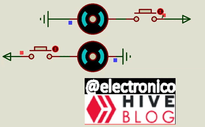
A DC motor with brushes is the simplest form of DC motors, it has only two terminals through which a voltage can be added and depending on the polarity of the applied voltage it will rotate in one direction or another. We can see this in the Proteus simulator.
A veces lo único que necesitas saber sobre un motor es donde conectarlo para que funcione, pero a veces... cuando necesitamos controlar ciertas variables que dependen de el sentido y velocidad de giro de un motor es necesario aprender a controlar estos valores.
Los motores AC y sus formas de control representan un tema muy amplio que probablemente abordemos en algún momento, sin embargo iniciaremos con motores DC ya que estos son muy utilizados en proyectos de robótica.
Un motor DC con escobillas es la forma más sencilla de motores DC, solo tiene dos terminales por los que se puede añadir un voltaje y dependiendo de la polaridad del voltaje aplicado va a girar en un sentido u otro. Podemos ver esto en el simulador Proteus.
Great! we have just discovered an important feature of DC motors with brushes, now we know that if we change the polarity in the power supply will change the direction of rotation.
The change in direction of rotation is important in such a large number of processes that it would lengthen the article just trying to complete the list, but we can summarize as a general aspect that allows us to move forward and backward in a process.
But I don't see myself with a pair of wires in my hand connecting and reversing connections on a motor every time I need to, so we must find a way to produce this polarity change without having to disconnect any wires.
To do this let's look at a switch arrangement known as an H-bridge by which the polarity of the power supply can be changed by combining the state of the switches.
¡Genial! acabamos de descubrir una característica importante de los motores DC con escobillas, ahora sabemos que si cambiamos la polaridad en la fuente de alimentación cambiará el sentido de giro.
El cambio de sentido en el giro es importante en una cantidad tan larga de procesos que alargaría el artículo con solo intentar completar la lista, pero podemos resumir como aspecto general que nos permite avanzar y retroceder en un proceso.
Pero no me veo con un par de cables en la mano conectando e invirtiendo conexiones en un motor cada vez que lo necesite, entonces debemos encontrar una forma de producir este cambio de polaridad sin tener que desconectar ningún cable.
Para ello veamos un arreglo de interruptores conocido como Puente H mediante el cual se puede cambiar la polaridad de la alimentación combinando el estado de los interruptores.
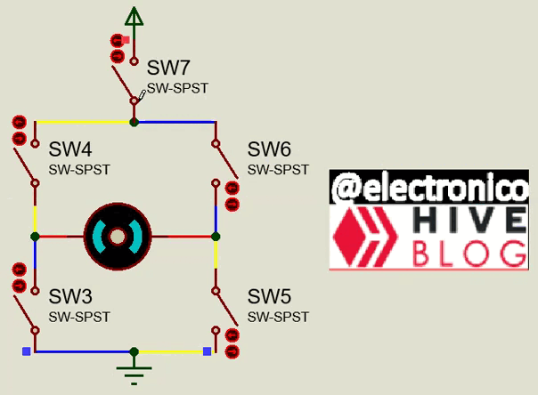
Here it is important to stop and observe carefully, the SW7 switch is the main switch and its only function is to allow or block the power supply.
I have marked the possible polarity routes with the colors blue and yellow, that is, by means of the jumper we are going to give a route to the current so that it crosses the motor and according to the route (blue or yellow) it will be the direction of rotation.
There is a very dangerous possibility that someone closes the wrong switches (SW3+SW4 or SW5+SW6), in this case we are making a direct path between the source and ground (short circuit) therefore this condition must be avoided at all costs.
Now a new issue arises and it is that we do not advance much from connecting and disconnecting wires to be opening and closing switches manually.
But we have already learned in previous articles that we can replace mechanical switches with transistors, indeed the first advantage we find is that instead of activating the switches one at a time they can be mixed as routes and a single signal can close two switches (transistors).
Let's see this in an example circuit.
Aquí es importante detenernos a observar cuidadosamente, el interruptor SW7 es el principal y su única función es la de permitir o bloquear la fuente de energía.
He marcado las rutas posibles de polaridad con los colores azul y amarillo, es decir, mediante el puente vamos a darle una ruta a la corriente para que atraviese el motor y según la ruta (azul o amarilla) será el sentido de giro.
Existe una muy peligrosa posibilidad de que alguien cierre los interruptores incorrectos (SW3+SW4 o SW5+SW6), en este caso estamos haciendo un camino directo entre la fuente y tierra (corto circuito) por lo tanto se debe evitar a toda costa esta condición.
Ahora surge una nueva cuestión y es que no avanzamos mucho desde estar conectando y desconectando cables a estar abriendo y cerrando interruptores de forma manual.
Pero ya hemos aprendido en artículos anteriores que podemos reemplazar interruptores mecánicos por transistores, en efecto la primera ventaja que encontramos es que en lugar de activar los interruptores de uno en uno se pueden mezclar como rutas y una sola señal puede cerrar dos interruptores (transistores).
Veamos esto en un circuito de ejemplo.

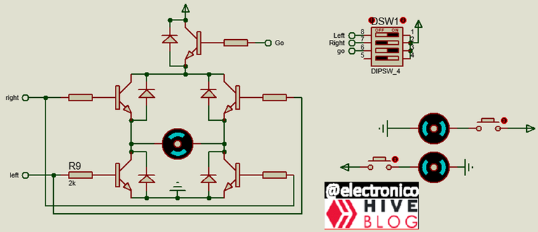
By using transistors we add the possibility of establishing an automatic control, in this way the switches are made by the system as we have programmed and we get rid of such a task, the diodes that have been added to each transistor are to protect them from the reverse peaks that can come from the motor by the effects of switching.
The truth is that although we have reduced the number of possible combinations in the switches, there is still a combination that generates a short circuit and that is when we operate both at the same time.
This can be eliminated definitively using a single switch and take the logical states 0 and 1 of that switch for each direction of rotation, if we want to stop the motor we can use the main switch to cut the power. To implement such control we add a NOT to the base of one of the transistors and take its state from the base of the other.
Al usar transistores añadimos la posibilidad de establecer un control automático, de esta forma las conmutaciones las hace el sistema según lo hayamos programado y nosotros nos libramos de semejante tarea, los diodos que se han agregado a cada transistor son para proteger a los mismos de los picos inversos que pueden provenir del motor por efectos de las conmutaciones.
Lo cierto es que aunque hemos reducido el número de combinaciones posibles en los interruptores aún sigue existiendo una combinación que genera un corto circuito y es cuando accionamos ambos a la vez.
Esto se puede eliminar de forma definitiva usando un solo conmutador y tomar los estados lógicos 0 y 1 de dicho conmutador para cada sentido de giro, si queremos detener el motor podemos usar el interruptor principal para cortar la energía. Para implementar dicho control añadimos una NOT a la base de uno de los transistores y tomamos su estado de la base del otro.
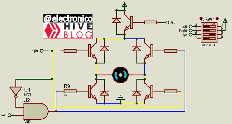
This completely eliminates the possibility of short-circuiting the combinations. Another way in which it would be possible to keep the two direction of rotation controls is to add a logical combination of and and Not as shown below.
De esta forma se elimina por completo la posibilidad de un corto circuito en las combinaciones. Otra forma en la que sería posible manteniendo los dos controles de sentido de giro es añadiendo una combinación lógica de and y Not como se muestra a continuación.
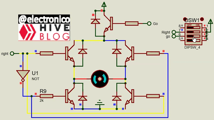
This H-bridge model allows to control the direction of rotation of a motor using a microcontroller, in this case the motor source can be greater than that supported by the microcontroller (but different from that used by the same or regulated), the activation current is supplied by the microcontroller but not the motor operation current.
Something we can notice is that when we make the H-bridge with BJT transistors the motor goes slower than when we use mechanical switches, this is due to the voltage drop that presents each BJT, the combination of drops is approximately 2V and must be taken into account when choosing the source of the motor knowing that this amount will be subtracted from the voltage that will finally reach the motor.
A solution comes if we replace the BJTs by Mosfets Transistors, but to be honest they already sell jumpers on a single integrated. What is exposed here is to help to understand the operation while we get into the subject (although you can also implement the circuits if you wish 😉).
Este modelo de puente H permite controlar el sentido de giro de un motor usando un microcontrolador, en este caso la fuente del motor puede ser mayor a la soportada por el microcontrolador (pero distinta a la usada por el mismo o regulada), la corriente de activación la suministra el microcontrolador pero no la de operación del motor.
Algo que podemos notar es que cuando hacemos el puente H con transistores BJT el motor va mas lento que cuando usamos interruptores mecánicos, esto se debe a la caída de voltaje que presenta cada BJT, la combinación de caídas es aproximadamente 2V y se deben tener en cuenta al momento de escoger la fuente del motor sabiendo que esta cantidad será restada del voltaje que finalmente llegará al motor.
Una solución viene si reemplazamos los BJT por Transistores Mosfets, pero siendo sincero ya venden puentes en un solo integrado. Lo expuesto aquí es para ayudar a comprender el funcionamiento mientras nos adentramos en el tema (aunque también puedes implementar los circuitos si lo deseas 😉).
Yay! 🤗
Your content has been boosted with Ecency Points, by @electronico.
Use Ecency daily to boost your growth on platform!
Support Ecency
Vote for new Proposal
Delegate HP and earn more
WOW, thank you so much!! 🤗
Thanks for your contribution to the STEMsocial community. Feel free to join us on discord to get to know the rest of us!
Please consider delegating to the @stemsocial account (85% of the curation rewards are returned).
Thanks for including @stemsocial as a beneficiary, which gives you stronger support.
Thank you!! Your are wonderful!!!