The I2C protocol EN/ES
So far we have seen 2 ways to communicate devices: Through USART and TIA485, both are serial communications with the first one it is only possible to communicate two devices on the same data bus, if you want to connect a third one you must do it through another port.
The second case improves the distances between the communication, both protocols are designed to communicate two devices and although we could adapt them to communicate microcontrollers that are united in the same electronic card it would be impractical, in addition there are elements like Displays, sensors and others that we could use in our projects that do not allow USART communication.
Thinking about this in the 80's Philips Semiconductor developed a protocol called I2C (Inter-Integrated Circuit) through which you can communicate different components that perform functions on the same electronic board with great benefits over other protocols such as fidelity, speed and the ability to connect up to 127 devices to the same communication bus. But let's continue with the article to go into details about this communication mode.
Hasta ahora hemos visto 2 formas de comunicar dispositivos: Mediante USART y TIA485, ambas son comunicaciones seriales con la primera solo es posible comunicar dos dispositivos en el mismo bus de datos, si se quiere conectar un tercero se debe hacer por otro puerto.
El segundo caso mejora las distancias entre la comunicación, ambos protocolos están diseñados para comunicar dos dispositivos y aunque pudiésemos adaptarlos para comunicar microcontroladores que estén unidos en una misma tarjeta electrónica resultaría poco práctico, además existen elementos como Displays, sensores y otros que podríamos usar en nuestros proyectos que no permiten comunicación USART.
Pensando en esto en los años 80 Philips Semiconductor desarrolló un protocolo llamado I2C (Inter-Integrated Circuit) mediante el cual se pueden comunicar distintos componentes que ejecutan funciones en una misma placa electrónica con grandes beneficios sobre los otros protocolos como fidelidad, velocidad y la posibilidad de conectar hasta 127 dispositivos al mismo bus de comunicación. Pero sigamos con el articulo para entrar en detalles sobre este modo de comunicación.

Representation of an I2C bus connection between several components.
Physical connections |
|---|
This communication mode uses two lines just like the previous ones but the difference is that data is only transmitted on one of them in a bidirectional way, this line is called SDA while the other line is used to synchronize the components and is called SCL.
Each component is directly connected to the bus on these two lines which means that the information sent on the bus is read by all components, for the correct interpretation of the message an address is set for the slaves (clients), the masters (servers) do not need address.
One of the main things to keep in mind is the way the data transmission is handled, being always the master the one who initiates the transmission process. If the master wants to send a data first establishes to whom it will be addressed and then sends the message, methods are established to verify the correct delivery, on the other hand if the master wants to read data from a slave it is the slave itself who initiates the process by sending a request with the address of the component to be consulted.
Note que en USART cualquier dispositivo podía transmitir por el bus incluso sin necesidad de que nadie lo solicite, para I2C solo el maestro decide quien envía y quien recibe. Todos se comunican con el maestro, ningún esclavo se comunica con otro esclavo. I2C también permite la existencia de varios maestros en el mismo bus.
Este modo de comunicación utiliza dos líneas igual que las anteriores pero la diferencia es que solo se transmiten datos por una de ellas de forma bidireccional, esta línea se llama SDA mientras que la otra línea se usa para sincronizar los componentes y se llama SCL.
Cada componente se conecta directamente al bus en estas dos líneas lo que significa que la información enviada en el bus es leída por todos los componentes, para la interpretación correcta del mensaje se establece una dirección para los esclavos (clientes), los maestros (servidores) no necesitan dirección.
Una de las principales cosas que debemos tener en cuenta es la forma como se maneja la transmisión de datos siendo siempre el maestro quien inicia el proceso de transmisión. Si el maestro desea enviar un dato establece primero a quien ira dirigido y luego envía el mensaje, se establecen métodos para verificar la correcta entrega, por otro lado si el maestro desea leer datos de algún esclavo es este mismo quien envía inicia el proceso enviando una solicitud con la dirección de aquel componente que desea consultar.
Note que en USART cualquier dispositivo podía transmitir por el bus incluso sin necesidad de que nadie lo solicite, para I2C solo el maestro decide quien envía y quien recibe. Todos se comunican con el maestro, ningún esclavo se comunica con otro esclavo. I2C también permite la existencia de varios maestros en el mismo bus.
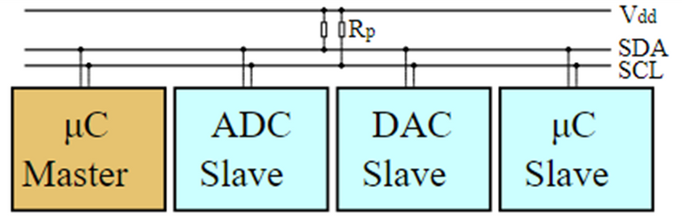
I2C. Author: Cburnett, Source: Wikimedia, license: This file is licensed under the Creative Commons Attribution-Share Alike 3.0 Unported
Data management |
|---|
Now we will deal with synchronous communication and "data packet", it means that this protocol establishes a combination between the SCL and SDA line to enable communication with a slave through its address and a change of state between both lines, once enabled it is indicated if you want to receive a data from the slave or transmit a data to it, The slave always sends confirmation that it has received the instruction and is ready to execute, then it sends the bit stream containing the data to be transmitted and ends with a confirmation bit, finally the master ends the communication with that element and leaves the bus ready for the next one.
To understand how each line acts in the transmission of each bit since the meaning of the bits in SDA is obtained according to the position of the bits in SCL. The structure for the frame is formed as follows:
➤ Start: when the SCL line is in a high state the master switches the SDA line from high to low generating a falling edge, this condition indicates that the bus will be used to communicate and all connected components start reading the message to identify to whom it is addressed(only the master can use the start bit).
➤ Address: After start the master sends 7bits containing the address of the component with which communication will be established, the slave having that address will be enabled to communicate.
➤ Read write: After the address the master sends a bit to indicate to the slave if it wants to read or write data to it.
➤ Acknowledge: The slave compares the address sent by the master with its own, if it matches it sends a modifies the SDA line to tell the master that it has received the message and is ready.
➤ Data: The data frame is sent in the address that has been set (read or write).
➤ Acknowledgement: The slave changes the SDA line again to indicate to the master that the transmission was successful.
➤ Stop: The master produces the stop to terminate the communication, it must now switch the SDA line from a low to a high state (rising edge) when the SCL line is high.
Ahora trataremos con comunicacion sincrona y "paquete de datos", quiere decir que este protocolo establece una combinación entre la línea SCL y SDA para habilitar la comunicación con un esclavo mediante su dirección y un cambio de estado entre ambas líneas, una vez habilitado se indica si se quiere recibir un dato desde el esclavo o transmitir un dato hacia el, el esclavo siempre envía confirmación de que ha recibido la instrucción y está listo para ejecutar, entonces se envía el tren de bits que contiene el dato a transmitir y se finaliza con un bit de confirmación, finalmente el maestro finaliza la comunicación con ese elemento y deja el bus listo para la siguiente.
Para comprender cómo actúa cada línea en la transmisión de cada bit ya que el significado de los bits en SDA se obtiene segun la posición de los bits en SCL. La estructura para la trama se forma como sigue:
➤ Inicio: Cuando la línea SCL está en un estado alto el maestro conmuta la línea SDA de alto a bajo generando un flanco de bajada, esta condición indica que se usará el bus para comunicar y todos los componentes conectados comienzan a leer el mensaje para identificar a quién va dirigido(solo el maestro puede usar el bit de inicio).
➤ Dirección: Luego del inicio el maestro envía 7bits que contienen la dirección del componente con el que se establecerá comunicación, el esclavo que tenga esa dirección se habilitará para comunicar.
➤ Lectura escritura: Después de la dirección el maestro envía un bit para indicarle al esclavo si desea leer o escribir datos en el.
➤ Confirmación: El esclavo compara la dirección enviada por el maestro con la suya propia, si coincide envía un modifica la línea SDA para indicarle al maestro que ha recibido el mensaje y está listo.
➤ Datos: Se envía la trama de datos en la dirección que se ha establecido (lectura o escritura).
➤ Confirmación: El esclavo vuelve a modificar la línea SDA para indicarle al maestro que la transmisión ha sido exitosa.
➤ Parada: El maestro produce la parada para finalizar la comunicación, ahora debe conmutar la línea SDA de un estado bajo a uno alto (flanco de subida) cuando la línea SCL esté en alto.
 I2c 7bit telegram. Author: VamosSandor, source: Wikimedia, license; This file is licensed under the Creative Commons Attribution-Share Alike 4.0 International
As we can see it presents a higher level of complexity but it also brings good benefits, especially because it will allow us to communicate even with other components that are not programmable such as LCDs, ADCs, memories and many others using only a couple of lines.
In the next article we will put all this theory into practice to increase understanding.
We will be able to say with what we have seen so far that for communication between a microcontroller and a computer we will use USART to RS232 (or usb), if we want to communicate our microcontroller with one or more devices that are far away we use TIA485 and if we want to communicate our microcontroller with another nearby microcontroller, electronic components like sensors, display, converters and others of the same nature, we will use I2C if it is available in these components, of course, after we learn how to do it in the next article. Until then 🖐.
Como podemos ver presenta un mayor nivel de complejidad pero también aporta buenos beneficios, especialmente porque nos permitirá comunicarnos incluso con otros componentes que no son programables como LCDs, ADCs, memorias y muchos otros usando solo un par de líneas.
En el siguiente artículo pondremos en práctica toda esta teoría para aumentar la comprensión.
Podremos decir con lo visto hasta ahora que para comunicación entre un microcontrolador y un ordenador usaremos USART a RS232 (o usb), si deseamos comunicar nuestro microcontrolador con uno o más dispositivos que se encuentran a grandes distancias usamos TIA485 y si deseamos comunicar nuestro microcontrolador con otro microcontrolador cercano, componentes electrónicos como sensores, display, conversores y otros de la misma naturaleza, usaremos I2C si está disponible en estos componentes, claro, después que aprendamos a hacerlo en el siguiente artículo. Hasta entonces 🖐.

Yay! 🤗
Your content has been boosted with Ecency Points, by @electronico.
Use Ecency daily to boost your growth on platform!
Support Ecency
Vote for new Proposal
Delegate HP and earn more
Thanks for your contribution to the STEMsocial community. Feel free to join us on discord to get to know the rest of us!
Please consider delegating to the @stemsocial account (85% of the curation rewards are returned).
You may also include @stemsocial as a beneficiary of the rewards of this post to get a stronger support.
Congratulations @electronico! You have completed the following achievement on the Hive blockchain And have been rewarded with New badge(s)
Your next target is to reach 5000 upvotes.
You can view your badges on your board and compare yourself to others in the Ranking
If you no longer want to receive notifications, reply to this comment with the word
STOPTo support your work, I also upvoted your post!
Check out our last posts:
Thank you @electronico