Showing sensor information in an LCD Screen (Multiple ADC Channels) - Mostrando informacion de sensores en una pantalla LCD (Multiples canales ADC) - Microcontrollers #5
Experimenting with ADCs
Shoutout to Simple Circuit

In this article you'll find:
- Introduction
- Multiple Channels in ADC
- Using two ADC channels
- Using the ADC with temperature sensors
Greetings to everyone in the Hive community!
For two editions now, we have been observing ADCs, unquestionably useful tools when it comes to making our microcontrollers understand signals from the outside world.
Until now, we have explained the concept of ADCs in detail and how to apply an individual channel to them. However, we still need to clarify some things.
From the use of multiple channels for our ADC to the practical application with sensors, all these will be topics that we will see today, in order to clarify our doubts and give us a complete mastery of these devices.
This way, if you want to be a master in handling ADCs in PIC, you just have to keep reading. Having said that:
Multiple Channels in ADC
Shoutout to Embedded Lab
As we had verified in the previous article, when we use the PIC C programming environment, it already has a library included that works with ADCs.
The instructions present in this are:
- setup_adc_ports() ; To configure which pin or pins will be the ADC channels.
- setup_adc() ; Selecting the conversion mode.
- setup_vref() ; If set to TRUE, we activate the reference voltage other than the supply.
- set_adc_channel() ; To go to the channel where we have the ADC information.
- read_adc(); To read the information of the selected ADC channel.
Instructions we used to create an ADC reader with a single channel. However, we do not have to relegate ourselves to a single ADC channel, since if we change the setup_adc_ports parameters, we can use more than one pin as an ADC channel and even determine that Vref+ and Vref-.
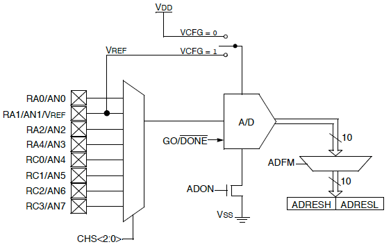
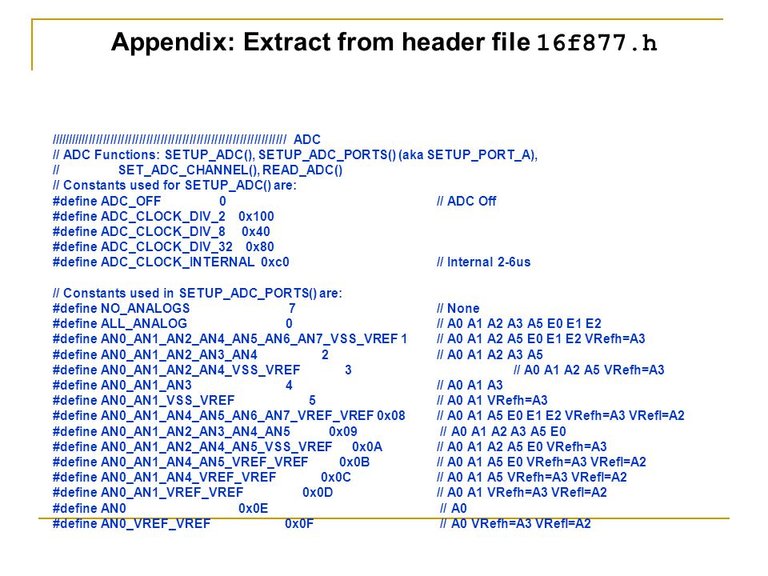
If we look at the image of the parameters available for setup_adc_ports and setup_adc:
Shoutout to Sheldon Gillam in SlidePlayer
Here we can notice that there are a large number of options, which allow us not only to take channel 0 (AN0), but also allow us other channels in turn, as can be seen in the parameters AN0_AN1_AN2_AN3_AN4 and in ALL_ANALOG, which allows us take all pins as analogues.
Additionally, if we want to configure the reference voltage high and low (this being the maximum value that the ADC will measure high and low), parameters such as AN0_AN1_VSS_VREF or AN0_AN1_AN4_VREF_VREF are used in conjunction with setup_vref(True) to activate the pins. AN2 and AN3 as the reference ones.
Now that we know how we can add additional channels to our PIC, let's see how this works in practice:
Using two ADC channels
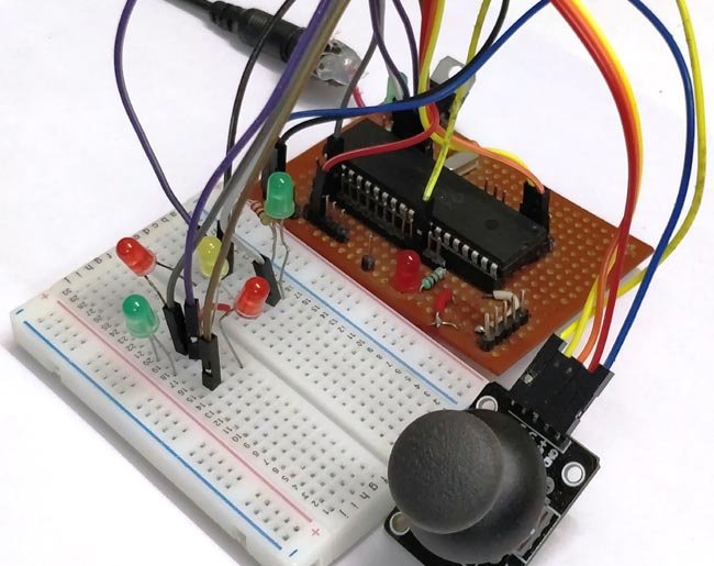
Shoutout to Circuit Digest
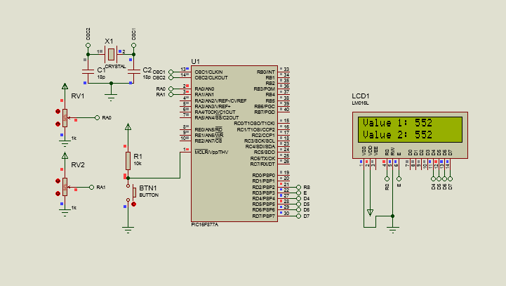
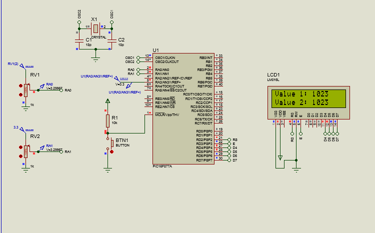
Taking a brief look at the connections, we can notice that little changes compared to the example in the previous edition. The only difference will be that now, instead of having a potentiometer connected to AN0, we will have two potentiometers, one with its output towards AN0 and the other towards AN1.
However, the most important thing to make this work will be the code, which we will see below:
#include <16f877a.h>
#fuses HS, NOWDT, NOPROTECT, NOPUT, NOLVP, BROWNOUT
#deviceADC = 10
#use delay(clock=20M)
#use standard_io(D)

#define LCD_DB4 PIN_D4
#define LCD_DB5 PIN_D5
#define LCD_DB6 PIN_D6
#define LCD_DB7 PIN_D7
#define LCD_RS PIN_D2
#define LCD_E PIN_D3
#include <LCD_16X2.c>

long adc_value;
long adc_value2;

void main()
{
    setup_adc_ports(AN0_AN1_AN3);
    lcd_init();
    setup_adc(adc_clock_internal);

    while(TRUE)
    {
       set_adc_channel(0);
       delay_us(2);
       adc_value = read_adc();

       set_adc_channel(1);
       delay_us(2);
       adc2value = read_adc();

       lcd_clear();
       lcd_gotoxy(1,1);
       printf(lcd_putc, "Value 1: %Lu", adc_value);

       lcd_gotoxy(1,2);
       printf(lcd_putc, "Value 2: %Lu", adc_value2);

       delay_ms(100);
    }
}
Here we notice a fairly standard procedure: We configure the header pins, we indicate that the ADC will be 10 bits, the clock 20MHz. Subsequently, we define the pins that will be dedicated to the LCD screen and include the library for it.
What does change will be adding another variable to store what we read from channel 1 (AN1) and now, when configuring the ports in the void main(), new parameters will be used for the setup_adc_ports(). In this case we will use AN0_AN1_AN3, to use the RA0, RA1 and RA3 pins as ADC channels. However, if you want to use more or fewer ADC channels, just check the table in the previous section and change it.
Also, inside the while loop, we notice that now the reading procedure (set_adc_channel with the channel number, small delay and storing the result of read_adc in a variable) will be repeated for both channels 0 and 1, in order of obtaining the values from both.
Then, we will only have to clear the screen and access rows 1 and 2 in the first positions to use a format string and thus print on the LCD screen the long value (Hence the %Lu) of both variables.
Seeing the result of this when executed, we would have:
According to the selected parameter, we could read the values of 1, 2, 4 or 8 sensors. Now we will see how to change the reference voltages so that 1023 represents a value of 3.3V and not 5V.
The first thing we have to do is use the setup_adc_ports() parameters that select Vref, such as: AN0_AN1_VREF_VREF or AN0_AN1_VSS_VREF. In this case we will use the second one, since we only want to change the upper reference voltage.
In addition to this, we use the setup_vref(TRUE), as reflected in the following code:
#include <16f877a.h>
#fuses HS, NOWDT, NOPROTECT, NOPUT, NOLVP, BROWNOUT
#deviceADC = 10
#use delay(clock=20M)
#use standard_io(D)

#define LCD_DB4 PIN_D4
#define LCD_DB5 PIN_D5
#define LCD_DB6 PIN_D6
#define LCD_DB7 PIN_D7
#define LCD_RS PIN_D2
#define LCD_E PIN_D3
#include <LCD_16X2.c>

long adc_value;
long adc_value2;

void main()
{
    setup_adc_ports(AN0_AN1_VSS_VREF);
    lcd_init();
    setup_adc(adc_clock_internal);
    setup_vref(TRUE);

    while(TRUE)
    {
       set_adc_channel(0);
       delay_us(2);
       adc_value = read_adc();

       set_adc_channel(1);
       delay_us(2);
       adc2value = read_adc();

       lcd_clear();
       lcd_gotoxy(1,1);
       printf(lcd_putc, "Value 1: %Lu", adc_value);

       lcd_gotoxy(1,2);
       printf(lcd_putc, "Value 2: %Lu", adc_value2);

       delay_ms(100);
    }
}
We can see that this is identical to the previous one, with the difference that the AN0_AN1_VSS_VREF is used to indicate that the RA0 and RA1 pins will be used as analog, while the AN3 pin will be used to change the reference voltage. In addition to this, we activate the setup_vref(TRUE) to activate AN2 and AN3 for these reference voltages.
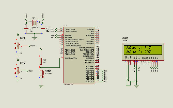
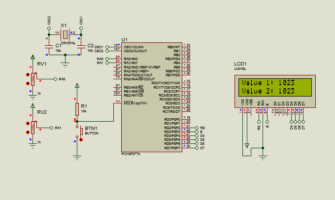
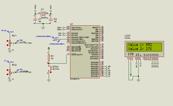
Now, if we look at the new connection:
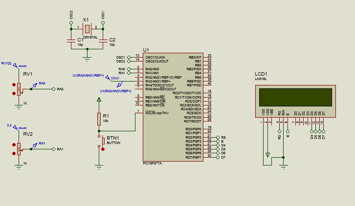
We notice that now in AN3 (Vref+), a DC voltage value of 3.3V will enter and that now, we will also have 3.3V connected to the power supply of the potentiometers. All of this will result in when you run the program, the 1023 of the ADCs will be displayed when the potentiometers lower their resistance value to allow the 3.3V to pass completely (A difference from the 1023 that was displayed with 5V previously).
Once we know how to use more than one channel on the ports for the ADC at the same time, we can move on to observe how the ADC works with a sensor.
Using the ADC with temperature sensors
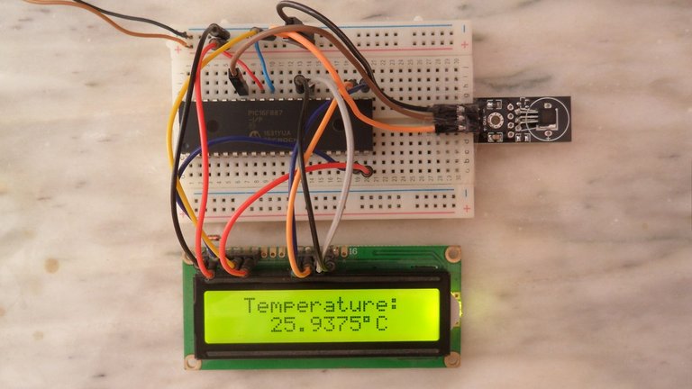
The best way to demonstrate how the ADC really works in practice will be through the use of a sensor, in this case a temperature sensor.
For the purposes of this tutorial, the LM35 will be used, a temperature sensor that allows us to measure values between -55 and 150 degrees Celsius, and can be powered with voltages between 4 and 20V, although the recommended value is 5V, which we will use .
It should be noted that what this sensor will do is that according to the temperature it measures in the room or place where it is located, it will return an analog output, which for each degree will return 10mV (e.g. if we have 27 degrees = 10mV * 27 = 0.27V)
This integrated device has 3 pins, among which we have:
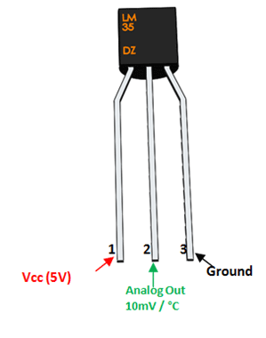
Shoutout to Components101
Where Vcc will be the power supply (The 5V that we will connect to this), GND will be the ground and Vo will be the analog output that will be connected to the pin dedicated to the ADC channel.
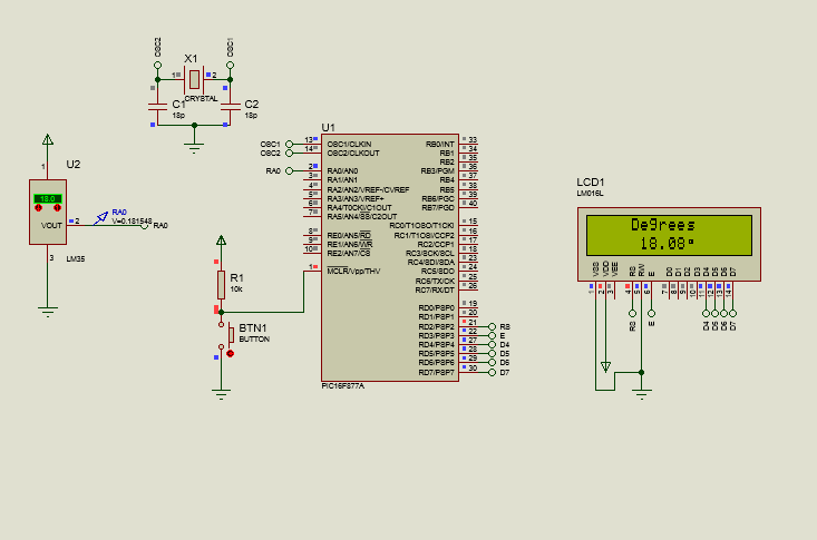
Now that we know how the LM35 works, we will see that the connection would be made as follows:
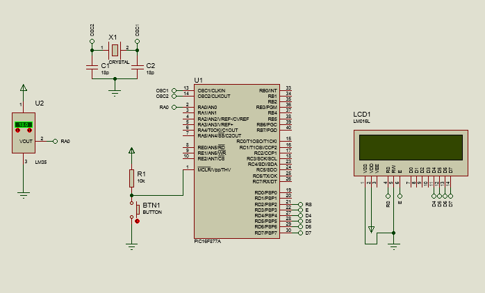
And regarding the code, we will create a new variable in addition to the adc value, which will be called temperature. This will contain a formula that will allow us to transform the digital value of the ADC into temperature values with the following equation:
temperature = adc_value*500
              -------------
                  1023.0
This would look like this:
#include <16f877a.h>
#fuses HS, NOWDT, NOPROTECT, NOPUT, NOLVP, BROWNOUT
#deviceADC = 10
#use delay(clock=20M)
#use standard_io(D)

#define LCD_DB4 PIN_D4
#define LCD_DB5 PIN_D5
#define LCD_DB6 PIN_D6
#define LCD_DB7 PIN_D7
#define LCD_RS PIN_D2
#define LCD_E PIN_D3
#include <LCD_16X2.c>

long adc_value;
float temperature;
char degrees[8] = {0x00,0x0E,0x0A,0x0E,0x00,0x00,0x00,0x00};

void main()
{
    setup_adc_ports(AN0);
    lcd_init();
    setup_adc(adc_clock_internal);
    CGRAM_position(0);
    CGRAM_create_char(degrees);

    while(TRUE)
    {
       set_adc_channel(0);
       delay_us(2);
       adc_value = read_adc();
       temperature = (adc_value * 500) / 1023.0;


       lcd_clear();
       lcd_gotoxy(5,1);
       lcd_putc("Degrees");

       lcd_gotoxy(6,2);
       printf(lcd_putc, "%0.2f", temperature);

       lcd_gotoxy(11,2);
       CGRAM_putc(0);

       delay_ms(100);
    }
}
Here, we can notice that in addition to creating a float variable for the temperature, which will have our formula, an array of type char is created. This is used to contain the values of the degree symbol, which we will save as a special character (If you want to know how to do this, read the next article).
Then, inside the void main(), we reconfigure just the RA0 as the ADC channel with setup_adc_ports, start the lcd, select the internal conversion mode, and then with CGRAM position we access the first position of the LCD's CGRAM and create as a character the value of the arrangement that we save.
For the while loop, we access channel 0 (RA0) and read its contents, storing it in adc_value, and then give a new temperature value, which will be the formula explained above, taking adc_value.
Then, what remains is simple. We clean the screen, we access the first row in column 4 to place "Temperature" and then to column 6 of row 2, to use a format string and place the temperature value as a float with two decimal places (%0.2 F). Finally, we place a small delay of 100ms.
Thus, when running the program after compiling:
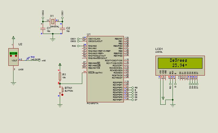
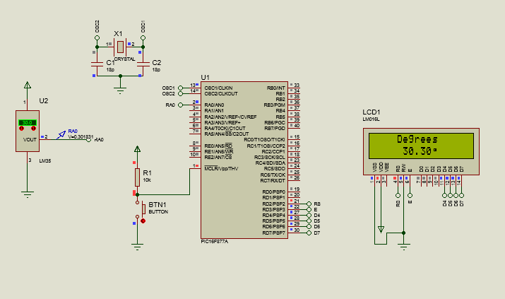
So we can notice that the values on the LCD increase as the temperature does. And in this way, we would have the application of the ADC with a sensor.
I hope that this article has been able to clearly show how the ADC can be used, not only individually on a single channel, but also with multiple ADCs together and their application with sensors.
In this way, you will already have knowledge that you can apply in your projects and that will be very helpful in subsequent editions. Soon, we will see what other sensors and peripherals can be used and how.
Having said that:

Experimentando con ADCs
Shoutout to Simple Circuit
In this article you'll find:
- Introducción
- Multiples Canales en ADC
- Usando dos canales ADC
- Usando el ADC con sensores de temperatura
Un saludo a todos en la comunidad de Hive!
Ya desde hace dos ediciones, hemos estado observando los ADCs, herramientas de utilidad indiscutible a la hora de hacer que nuestros microcontroladores entiendan las señales del mundo exterior.
Hasta ahora, hemos explicado el concepto de los ADC en detalle y como aplicar un canal individual a estos. Sin embargo, todavía nos falta clarificar algunas cosas.
Desde el uso de múltiples canales para nuestro ADC hasta la aplicación práctica con sensores, todos estos serán tópicos que veremos hoy, en orden de clarificar nuestras dudas y darnos un dominio total de estos dispositivos.
De esta forma, si quieres ser un maestro en el manejo de los ADC en PIC, solo tienes que seguir leyendo. Dicho esto:
Multiples Canales en ADC
Shoutout to Embedded Lab
Como habíamos verificado en el artículo anterior, cuando usamos el entorno de programación de PIC C, este ya tiene incluido una librería que trabaja con ADCs.
Las instrucciones presentes en esta son:
- setup_adc_ports() ; Para configurar que pin o pines serán los canales ADC.
- setup_adc() ; Seleccionando el modo de conversión.
- setup_vref() ; Si se coloca en TRUE, activamos el voltaje de referencia distinto a la alimentación.
- set_adc_channel() ; Para ir al canal donde tenemos la información del ADC.
- read_adc(); Para leer la información del canal ADC seleccionado.
Instrucciones que usamos para crear un lector de ADC con un solo canal. Sin embargo, no tenemos que relegarnos a un solo canal del ADC, ya que si cambiamos los parámetros del setup_adc_ports, podremos usar más de un pin como canal ADC e incluso determinar que Vref+ y Vref-.
Si observamos la imagen de los parámetros disponibles para setup_adc_ports y setup_adc:
Shoutout to Sheldon Gillam in SlidePlayer
Aquí podremos notar que hay una gran cantidad de opciones, que nos permiten no solo tomar el canal 0 (AN0), sino que también nos permiten otros canales a su vez, como se puede observar en los parámetros AN0_AN1_AN2_AN3_AN4 y en ALL_ANALOG, que nos permite tomar todos los pines como análogos.
Además, si queremos configurar el voltaje de referencia en alto y en bajo (Este siendo el máximo valor que medirá el ADC en alto y en bajo), se usan parámetros como el AN0_AN1_VSS_VREF o AN0_AN1_AN4_VREF_VREF en conjunto con setup_vref(True) para activar los pines AN2 y AN3 como los de referencia.
Ahora que sabemos como podemos agregar canales adicionales a nuestro PIC, veamos como funciona esto en la práctica:
Usando dos canales ADC
Shoutout to Circuit Digest
Dando un vistazo breve a las conexiones, podemos notar que poco cambia respecto al ejemplo de la edición anterior. La única diferencia será que ahora, en vez de tener un potenciómetro conectado a AN0, tendremos dos potenciómetros, uno con su salida hacia AN0 y el otro hacia AN1.
Sin embargo, lo más importante para hacer esto funcionar será el código, el cual veremos a continuación:
#include <16f877a.h>
#fuses HS, NOWDT, NOPROTECT, NOPUT, NOLVP, BROWNOUT
#device ADC = 10
#use delay(clock=20M)
#use standard_io(D)

#define LCD_DB4 PIN_D4
#define LCD_DB5 PIN_D5
#define LCD_DB6 PIN_D6
#define LCD_DB7 PIN_D7
#define LCD_RS PIN_D2
#define LCD_E PIN_D3
#include <LCD_16X2.c>

long valor_adc;
long valor_adc2;

void main()
{
   setup_adc_ports(AN0_AN1_AN3);
   lcd_init();
   setup_adc(adc_clock_internal);

   while(TRUE)
   {
      set_adc_channel(0);
      delay_us(2);
      valor_adc = read_adc();

      set_adc_channel(1);
      delay_us(2);
      valor_adc2 = read_adc();

      lcd_clear();
      lcd_gotoxy(1,1);
      printf(lcd_putc, "Value 1: %Lu", valor_adc);

      lcd_gotoxy(1,2);
      printf(lcd_putc, "Value 2: %Lu", valor_adc2);

      delay_ms(100);
   }
}
Aquí notamos un procedimiento bastante estándar: Configuramos los pines de cabecera, indicamos que el ADC será de 10 bits, el reloj de 20MHz. Posteriormente, definimos los pines que se dedicarán a la pantalla LCD e incluímos la librería para este.
Lo que si cambia, será el añadir otra variable, para almacenar lo que leamos del canal 1 (AN1) y que ahora, al configurar en el void main() los puertos, se usarán nuevos parámetros para el setup_adc_ports(). En este caso usaremos AN0_AN1_AN3, para usar los pines RA0, RA1 y RA3 como canales ADC. Sin embargo, si quieres usar más o menos canales ADC, solo debes de verificar la tabla en la sección anterior y cambiarlo.
Además, dentro del ciclo while, notamos que ahora el procedimiento de lectura (set_adc_channel con el número del canal, pequeño retardo y almacenar el resultado de read_adc en una variable) se repetirá tanto para los canales 0 y 1, en orden de obtener los valores de ambos.
Luego, solo tendremos que limpiar la pantalla y acceder a las filas 1 y 2 en las primeras posiciones para usar un format string y así imprimir en la pantalla del LCD en valor long (De ahí el %Lu) de ambas variables.
Viendo el resultado de esto al ejecutar, tendríamos:
De acuerdo al parámetro seleccionado, podríamos leer los valores de 1, 2, 4 u 8 sensores. Ahora veremos como cambiar los voltajes de referencia para que el 1023 represente un valor de 3.3V y no 5V.
Lo primero que tenemos que hacer es usar los parámetros de setup_adc_ports() que seleccionen a Vref, como lo son: AN0_AN1_VREF_VREF o AN0_AN1_VSS_VREF. En este caso usaremos la segunda, ya que solo queremos cambiar el voltaje de referencia superior.
Además de esto, empleamos el setup_vref(TRUE), como se ve reflejado en el siguiente código:
#include <16f877a.h>
#fuses HS, NOWDT, NOPROTECT, NOPUT, NOLVP, BROWNOUT
#device ADC = 10
#use delay(clock=20M)
#use standard_io(D)

#define LCD_DB4 PIN_D4
#define LCD_DB5 PIN_D5
#define LCD_DB6 PIN_D6
#define LCD_DB7 PIN_D7
#define LCD_RS PIN_D2
#define LCD_E PIN_D3
#include <LCD_16X2.c>

long valor_adc;
long valor_adc2;

void main()
{
   setup_adc_ports(AN0_AN1_VSS_VREF);
   lcd_init();
   setup_adc(adc_clock_internal);
   setup_vref(TRUE);

   while(TRUE)
   {
      set_adc_channel(0);
      delay_us(2);
      valor_adc = read_adc();

      set_adc_channel(1);
      delay_us(2);
      valor_adc2 = read_adc();

      lcd_clear();
      lcd_gotoxy(1,1);
      printf(lcd_putc, "Value 1: %Lu", valor_adc);

      lcd_gotoxy(1,2);
      printf(lcd_putc, "Value 2: %Lu", valor_adc2);

      delay_ms(100);
   }
}
Podemos ver que este es idéntico al anterior, con la diferencia de que se usa el AN0_AN1_VSS_VREF para indicar que se usarán los pines RA0 y RA1 como analógicos, mientras que el pin AN3 se usará para cambiar el voltaje de referencia. Además de esto, activamos el setup_vref(TRUE) para activar AN2 y AN3 para estos voltajes de referencia.
Ahora, si observamos la nueva conexión:
Notamos que ahora en AN3 (Vref+), entrará un valor de voltaje de DC de 3.3V y que ahora, también tendremos 3.3V conectados a la alimentación de los potenciómetros. Todo esto resultará en que al ejecutar el programa, se muestren los 1023 de los ADC cuando los potenciómetros bajen su valor de resistencia para permitir que los 3.3V pasen por completo (Una diferencia de los 1023 que se mostraban con 5V anteriormente).
Una vez que sabemos como usar más de un canal en los puertos para el ADC al mismo tiempo, podemos pasar a observar como sería el funcionamiento del ADC con un sensor.
Usando el ADC con sensores de temperatura
La mejor forma de demostrar como funciona realmente el ADC en la práctica será por medio del uso de un sensor, en este caso una de temperatura.
Para efectos de este tutorial se usará el LM35, un sensor de temperatura que nos permite medir valores de entre -55 y 150 grados celsius, pudiendo ser alimentado con voltajes de entre 4 y 20V, aunque el valor recomendado es de 5V, el cual usaremos.
Cabe notar que lo que hará este sensor es que de acuerdo a la temperatura que mida en la habitación o el lugar donde se encuentre, este nos devolverá una salida analógica, la cual por cada grado nos devolverá 10mV (Ej. Si tenemos 27 grados = 10mV * 27 = 0.27V)
Este integrado tiene 3 pines, entre los cuales tenemos:
Shoutout to Components101
Donde Vcc será la alimentación (Los 5V que conectaremos a este), GND será la tierra y el Vo será la salida analógica que irá conectada al pin dedicado al canal ADC.
Ahora que conocemos como funciona el LM35, veremos que la conexión se realizaría de la siguiente manera:
Y con respecto al código, crearemos una nueva variable además de la del valor del adc, la cual se llamará temperatura. Esta contendrá una fórmula que nos permitirá transformar el valor digital del ADC en valores de temperatura con la siguiente ecuación:
temperatura =  valor_adc*500
               -------------
                   1023.0
Esto se vería de la siguiente forma:
#include <16f877a.h>
#fuses HS, NOWDT, NOPROTECT, NOPUT, NOLVP, BROWNOUT
#device ADC = 10
#use delay(clock=20M)
#use standard_io(D)

#define LCD_DB4 PIN_D4
#define LCD_DB5 PIN_D5
#define LCD_DB6 PIN_D6
#define LCD_DB7 PIN_D7
#define LCD_RS PIN_D2
#define LCD_E PIN_D3
#include <LCD_16X2.c>

long valor_adc;
float temperatura;
char grados[8] = {0x00,0x0E,0x0A,0x0E,0x00,0x00,0x00,0x00};

void main()
{
   setup_adc_ports(AN0);
   lcd_init();
   setup_adc(adc_clock_internal);
   CGRAM_position(0);
   CGRAM_create_char(grados);

   while(TRUE)
   {
      set_adc_channel(0);
      delay_us(2);
      valor_adc = read_adc();
      temperatura = (valor_adc * 500) / 1023.0;


      lcd_clear();
      lcd_gotoxy(5,1);
      lcd_putc("Degrees");

      lcd_gotoxy(6,2);
      printf(lcd_putc, "%0.2f", temperatura);

      lcd_gotoxy(11,2);
      CGRAM_putc(0);

      delay_ms(100);
   }
}
Aquí, podemos notar que además de crear una variable float para la temperatura, la cual tendrá nuestra fórmula, se crea un arreglo de tipo char. Este se usa para contener los valores del símbolo de grados, el cual guardaremos como caracter especial (Si quieres saber como hacer esto, lee el siguiente artículo).
Luego, dentro del void main(), volvemos a configurar solo el RA0 como canal ADC con setup_adc_ports, iniciamos el lcd, seleccionamos el modo de conversión interno, y luego, con CGRAM position accedemos a la primera posición de la CGRAM del LCD y creamos como caracter el valor del arreglo que guardamos.
Para el ciclo while, Accedemos al canal 0 (RA0) y leemos el contenido de este, almacenándolo en valor_adc, para luego dar un nuevo valor a temperatura, que será la fórmula explicada anteriormente, tomando a valor_adc.
Luego, lo que queda es sencillo. Limpiamos la pantalla, accedemos a la primera fila en la columna 4 para colocar "Temperatura" y luego a la columna 6 de la fila 2, para usar un format string y colocar el valor de la temperatura como un float con dos decimales (%0.2f). Finalmente, colocamos un pequeño retardo de 100ms.
Así, al ejecutar el programa tras compilar:
Con lo que podemos notar que los valores en el LCD aumentan a la par que la temperatura lo hace. Y de esta forma, tendríamos la aplicación del ADC con un sensor.
Espero que este artículo haya podido mostrar de forma clara como se puede usar el ADC, no solo de manera individual en un solo canal, sino también con multiples ADC en conjunto y su aplicación con sensores.
De esta forma, ya tendrás conocimiento que podrás aplicar en tus proyectos y que nos servirá de mucha ayuda en ediciones posteriores. Proximamente, veremos que otros sensores y periféricos se pueden usar y como.
Dicho esto:
Pregunto desde mi desconocimiento, que lenguaje de programación se necesita saber para hacer eso mismo?
Saludos bro. Para trabajar con microcontroladores PIC y hacer lo mismo que en este tutorial se usa lenguaje C.
También existe otra forma de trabajar con microcontroladores PIC que es un poco más antigua, la cual es usar Assembler. Sin embargo, con C puedes hacer todo facilmente.
It is always interesting to see the programing background of microcontrollers hehehe it is something that still I didn't do.
Want to Know more about Hivepakistan?
Ping Us On Hive Pakistan Discord server
To support HivePakistan, delegate Hive Power to hivepakistan and earn 90% curation reward :)
Here are some handy links for delegation
A delegation of 500 or more HP makes you earn Hivepakistan supporter badge.
It sure is interesting! If you decide to start working with microcontrollers, I recommend you use a PIC or an Arduino, but It will ultimately be up to you.
Thank you for the support!
Thanks for your contribution to the STEMsocial community. Feel free to join us on discord to get to know the rest of us!
Please consider delegating to the @stemsocial account (85% of the curation rewards are returned).
You may also include @stemsocial as a beneficiary of the rewards of this post to get a stronger support.