Using 2 or more 7 segment displays with 1 port | Usando 2 o más displays de 7 segmentos con 1 puerto - Microntroladores #7
Using multiple displays
Shoutout to Embedded Lab

In this article you will find:
- Introduction
- How can we manage two displays at the same time?
- Connections
- Setting the code
Greetings to all!
I'm glad you liked the previous article. 7-segment displays were of great importance in electronic display in previous decades, and are currently considered for vintage-style equipment.
However, knowing about these gives us the basis to be able to understand more complex displays.
Until now, we have worked with a single 7-segment display. But, what happens if we want to work with more than two displays?
We can do this in two ways:
- Use the corresponding pins of each port of our microcontroller to provide sequences to the displays (For example, pins 0 to 7 on port A for display 1, pins 0 to 7 of port B for display 2, etc...)
- Send values to multiple displays using only the pins of one port.
The first option represents a huge expense of pins that we can use for many more functions such as adding buttons, sensors or other displays, so it is not applied.
Instead, the second option is used, where the pins are taken from just one port and then additional pins are used that will disable and enable each display as appropriate.
This phenomenon, through which information is transmitted to several peripherals through a single medium, is quite similar to multiplexing (Sending information from several channels through a single medium or signal), a topic that we will study in a later article.
So, if you want to know how to manage 2 7-segment displays together, you just have to keep reading. Having said that:
How can we manage two displays at the same time?
Shoutout to microdigisoft.com
I know that managing two displays at the same time with the same port sounds counterintuitive, since two different ports would be needed to send quantity information to the displays.
You are correct, managing two displays at the same time and doing it with the 7 pins of a single port is impossible, but we can do something quite interesting: We can turn on one display and turn off the other at one time and at another time turn on the display remaining and turn off the previous display.
We repeat this cycle very quickly so that in this way we fool the human eye and make it think that the figure appears the same all this time.
For example, if we have two 7-segment displays and we want to show the number 10, what we would have to do is first turn off the tens display (1) and turn on the units display (0). This would be maintained for 4 ms and then turn off the display at 0 and turn on the one at 1, also holding for 4 ms.

This will be enough for us to see the illusion that both displays are on at the same time.
This will be true for the number of displays required. However, we must take into account that the more displays, the less time per instruction will be required, so it is recommended to use higher frequency crystals.
Now let's look at the connections
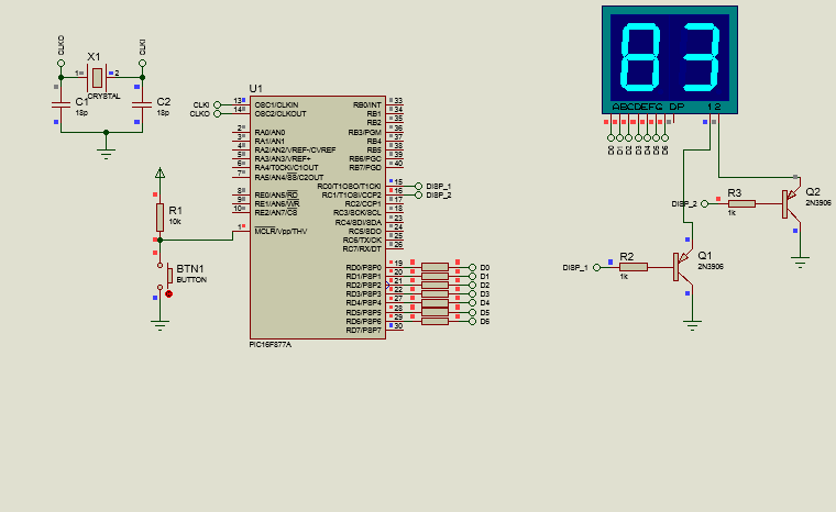
Connections

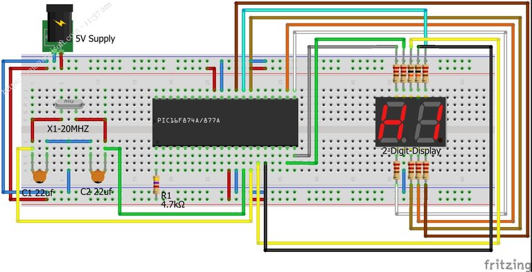
Following what was described in the previous section, we take the pins of port D (Minus pin 7) and connect them to segments a,b,c,d,e,f and g of the display array, which are simply two common cathode displays which we can deactivate or activate by placing pins 1 and 2 low (active) or high (off).
Thus, since the displays contain blue LEDs, which have a threshold voltage of 3.3 V and require a current of 20-30mA, we do the calculation for the resistors:
Res =  Vcc - Vf
       ---------
          Io

    =  5 - 3.3
      ---------
       30x10^-3

    = 56.66Ω
With which you can select the closest commercial resistance value, 56Ω, which will be the value of all the resistors connected to the segments.
In the case of pins 1 and 2, which allow us to activate and deactivate the display, we connect the pnp transistor collectors to them so that they work as switches, which will mean that when the output of PIN RC0 is high, it will also be high. the input of 1, which will make the display turn off, since it is a common cathode (This pin requires being grounded to display information). Otherwise, if the RC0 output is low, then 1 will also be low and therefore, we can see the display on the left.
For pin 2 of the display array, it will be the same. If RC1 is high, then 2 will also be high and we will not see the units display. If it is low, then we can see it.
Thus, we can understand the connections and move to the heart of the program: The code.
Setting the code
Here we will see two programs that will give us tests of how we can show information of two different values on displays with the same port.
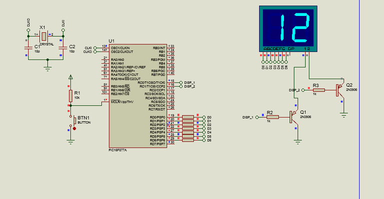
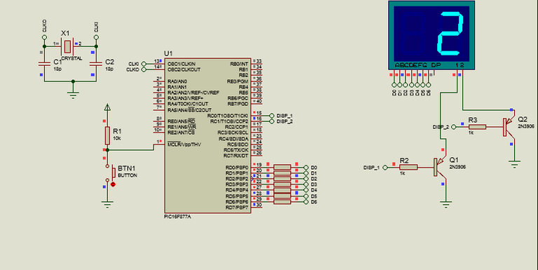
The first will be a simple program, with which we can see the number 12 on our displays. For this, we remember that the shorter the delay time between turning on one display and turning off the other, the more we will see the illusion of two numbers at the same time.
Thus, all that remains is to observe the following code:
#include <16f877a.h>
#fuses HS, NOWDT, NOPROTECT, NOPUT, NOLVP, BROWNOUT
#use delay(clock=20M)
#use fast_io(D)
#use standard_io(C)

#define DISPLAY_1 PIN_C0
#define DISPLAY_2 PIN_C1

int display[10] = {0x3F, 0x06, 0x5B, 0x4F, 0x66, 0x6D, 0x7D, 0x07, 0x7F, 0x6F};

void main()
{
    set_tris_d(0x00);

    while(TRUE)
    {
       output_high(DISPLAY_2);
       output_low(DISPLAY_1);
       output_d(display[1]);
       delay_ms(4);

       output_high(DISPLAY_1);
       output_low(DISPLAY_2);
       output_d(display[2]);
       delay_ms(4);
    }
}
Here, we can see that pins C0 and C1 are configured as those belonging to the display (We assign them a new name to work with them with define), we create the arrangement concerning the display numbers. If you want to know how these numbers are created, take a look at the previous article
Furthermore, once we are in the main, thanks to the fast_io(D) directive, we can determine that the pins of port d will be used exclusively as outputs with the set_tris_d(0x00) instruction.
Then, within the while(TRUE) we begin by placing DISPLAY_2 (C1) high to turn on the units display and we place Pin C1 (DISPLAY_1 within the code) low to turn off the tens array.
After doing this, we place the output of pin D corresponding to decimal 1, which in binary would be 00000001 and we place a delay of 4ms, which will be enough for the user not to notice the change.
Then, we repeat the same thing, now placing DISPLAY_1 (tens) high and DISPLAY_2 (units) low, waiting again for another 4 ms.
Once our simulation is compiled and running, we will see the following:
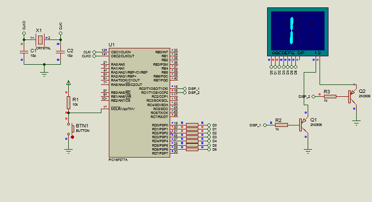
Value that will not seem to change at any time. If you are wondering what everything would look like if the delay time were longer, say about 500 ms, we would see the following:
Now that we know how to create this, we can move on to the next program, where we will create a counter from 0 to 99.
In order to do this, not much changes. We just have to keep in mind that we are going to take a variable that must increase constantly, which is why counters will be created.
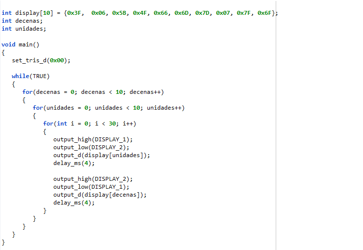
Now, since we are handling both units and tens, we will need to create two counters. And once we create them, simply with the help of for loops we will do the rest. If we look at the following code:
#include <16f877a.h>
#fuses HS, NOWDT, NOPROTECT, NOPUT, NOLVP, BROWNOUT
#use delay(clock=20M)
#use fast_io(D)
#use standard_io(C)

#define DISPLAY_1 PIN_C0
#define DISPLAY_2 PIN_C1

int display[10] = {0x3F, 0x06, 0x5B, 0x4F, 0x66, 0x6D, 0x7D, 0x07, 0x7F, 0x6F};
int tens;
int units;

void main()
{
    set_tris_d(0x00);

    while(TRUE)
    {
       for(tens = 0; tens < 10; tens++)
       {
          for(units = 0; units < 10; units++)
          {
             for(int i = 0; i < 30; i++)
             {
                output_high(DISPLAY_1);
                output_low(DISPLAY_2);
                output_d(display[units]);
                delay_ms(4);

                output_high(DISPLAY_2);
                output_low(DISPLAY_1);
                output_d(display[tens]);
                delay_ms(4);
             }
          }
       }
    }
}
After creating the array, the integer type variables that we will use for the counters are created, and once we are in the while loop, we begin by creating a for loop for the tens, which will take the tens variable, starting at zero and increment it as long as its value is less than 9.
However, this will only increase the tens, and at the same time we want the number of tens to only increase once the number 9 is exceeded in the ones. This is why we created a nested for loop for the units, following the same principle.
Units starts at 0 and is incremented as long as the value is less than 10. Then, the next for loop is only created for the purposes of creating a 30ms delay so we can watch the value change occur.
Within this, we repeat the same thing, alternating between activating display 1 and display 2 while the values of the counters are displayed with a delay of 4ms.
So, if we saw how this is executed, we would have:
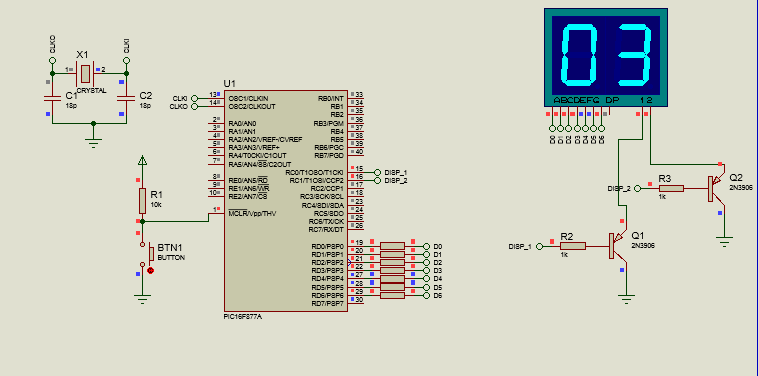

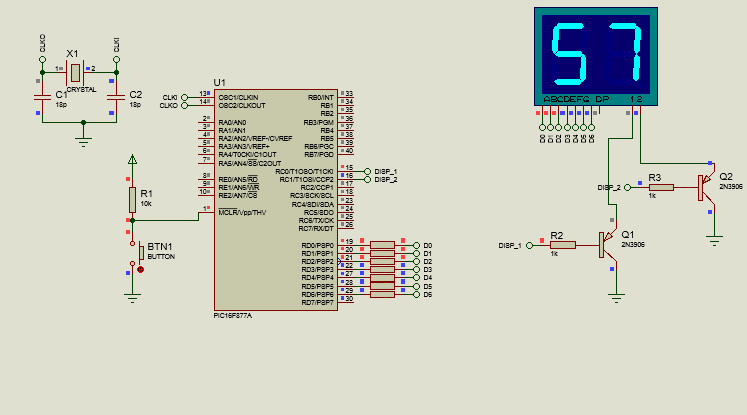
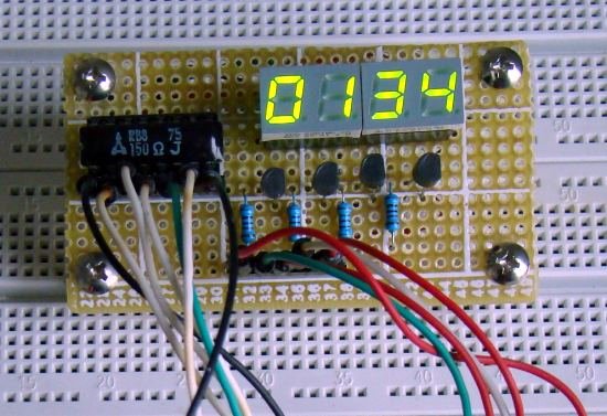
And so, we would have our counter from 0 to 99 with two 7-segment displays.
As you can see, regardless of the number of Displays, we can always find a way to display different values without having to use more than one port.
We just have to learn to fool the human eye to accomplish our task in an affordable way and thus leave the rest of the ports available for any other function that we want to add to our program.
Once we finish with the 7-segment displays, it is time to look at other display elements such as LED matrices, which will be the topic we will talk about in the next edition of microcontrollers.
In this way, I wish you a happy weekend, as well as:

Usando multiples Displays
Shoutout to Embedded Lab
En este artículo encontrarás:
- Introduccion
- ¿Cómo podemos manejar dos displays al mismo tiempo?
- Conexiones
- Estableciendo el código
!Un saludo a todos!
Me alegra que les haya gustado el artículo anterior. Los display de 7 segmentos fueron de gran importancia en la visualización electrónica en decadas anteriores, y actualmente son considerados para equipos de estilo vintage.
Sin embargo, el conocer sobre estos nos da las bases para poder entender displays de mayor complejidad.
Hasta ahora, hemos trabajado con un solo display de 7 segmentos. Pero, ¿Qué pasa si queremos trabajar con más de dos displays?
Podemos hacer esto de dos formas:
- Usar los pines correspondientes de cada puerto de nuestro microcontrolador para brindar secuencias a los displays (Por ejemplo, los pines del 0 al 7 en el puerto A para el display 1, los pines del 0 al 7 del puerto B para el display 2, etc...)
- Enviar valores a multiples displays usando solo los pines de un puerto.
La primera opción nos representa un gasto enorme de pines que podemos utilizar para muchas más funciones como añadir botones, sensores u otros displays, por lo que no es aplicada.
En cambio, se usa la segunda opción, donde se toman los pines de solo un puerto y luego, se usan pines adicionales que desactivarán y activarán cada display según sea conveniente.
Este fenómeno, por medio del cual se transmite información a varios periféricos por medio de un solo medio es bastante similar a la multiplexación (Envio de información de varios canales por un solo medio o señal), tema que estudiaremos en un artículo posterior.
Así, si quieres saber como manejar 2 displays de 7 segmentos en conjunto, solo tienes que seguir leyendo. Dicho esto:
¿Cómo podemos manejar dos displays al mismo tiempo?
Shoutout to microdigisoft.com
Sé que manejar dos displays al mismo tiempo con el mismo puerto suena contraintuitivo, ya que se necesitarían dos puertos distintos para enviar información de las cantidades a los displays.
Estás en lo correcto, manejar dos displays al mismo tiempo y hacerlo con los 7 pines de un solo puerto es imposible, pero si podemos hacer algo bastante interesante: Podemos encender un display y apagar el otro en un momento y en otro momento encender el display restante y apagar el display anterior.
Repetimos este ciclo muy rápidamente para que de esta forma, engañemos al ojo humano y le hagamos pensar que la figura se muestra igual todo este tiempo.
Por ejemplo, si tenemos dos displays de 7 segmentos y queremos mostrar el número 10, lo que tendríamos que hacer es primero apagar el display de las decenas (1) y encender el de las unidades (0). Esto se mantendría por 4ms para luego apagar el display que tiene al 0 y encender el del 1, también manteniendo por 4 ms.

Esto será suficiente para que veamos la ilusión de que los dos displays están encendidos al mismo tiempo.
Esto será cierto para la cantidad de displays que se requiera. Sin embargo, debemos de tomar en cuenta que mientras más displays, se requerirá un tiempo por instrucción menor, por lo que se recomienda usar cristales de mayor frecuencia.
Ahora, veamos las conexiones
Conexiones
Siguiendo lo descrito en la sección anterior, tomamos los pines del puerto D (Menos el pin 7) y los conectamos a los segmentos a,b,c,d,e,f y g del arreglo de displays, que son simplemente dos displays de cátodo común los cuales podemos desactivar o activar al colocar los pines 1 y 2 en bajo (activo) o en alto (apagado).
Así, ya que los displays contienen leds azules, los cuales tienen un voltaje de umbral de 3,3 V y requieren una corriente de 20-30mA, hacemos el cálculo para las resistencias:
Res =  Vcc - Vf
      ---------
         Io

    =  5 - 3.3
      ---------
       30x10^-3

    =  56,66Ω
Con lo que se puede seleccionar el valor de resistencia comercial más cercano, 56Ω, que será el valor de todas las resistencias conectadas a los segmentos.
En el caso de los pines 1 y 2, que nos permiten activar y desactivar al display, conectamos a estos los colectores de transistores pnp para que trabajen como interruptores, lo que hará que cuando la salida del PIN RC0 esté en alto, también lo esté la entrada de 1, lo que hará que el display se apague, ya que es de cátodo común (Este pin requiere estar a tierra para mostrar información). En caso contrario, si la salida RC0 está en bajo, entonces 1 también lo estará y por lo tanto, podremos ver el display de la izquierda.
Para el pin 2 del arreglo de displays, será lo mismo. si RC1 está en alto, entonces 2 también lo estará y no veremos el display de las unidades. Si está en bajo, entonces si lo podremos ver.
Así, ya podremos entender las conexiones y pasar al corazón del programa: El código.
Estableciendo el código
Aquí veremos dos programas que nos darán pruebas de como podemos mostrar información de dos valores distintos en displays con el mismo puerto.
El primero, será un programa sencillo, con el que podremos ver el número 12 en nuestros displays. Para esto, recordamos que mientras menor sea el tiempo de retardo entre el encendido de un display y el apagado del otro, más veremos la ilusión de dos números al mismo tiempo.
Así, solo resta observar el siguiente código:
#include <16f877a.h>
#fuses HS, NOWDT, NOPROTECT, NOPUT, NOLVP, BROWNOUT
#use delay(clock=20M)
#use fast_io(D)
#use standard_io(C)

#define DISPLAY_1 PIN_C0
#define DISPLAY_2 PIN_C1

int display[10] = {0x3F,  0x06, 0x5B, 0x4F, 0x66, 0x6D, 0x7D, 0x07, 0x7F, 0x6F};

void main()
{
   set_tris_d(0x00);

   while(TRUE)
   {
      output_high(DISPLAY_2);
      output_low(DISPLAY_1);
      output_d(display[1]);
      delay_ms(4);

      output_high(DISPLAY_1);
      output_low(DISPLAY_2);
      output_d(display[2]);
      delay_ms(4);
   }
}
Aquí, podemos observar que se configuran los pines C0 y C1 como los pertenecientes al display (Les asignamos un nuevo nombre para trabajar con estos con define), creamos el arreglo concerniente a los números del display. Si quieres saber como se crean estos números, echa un vistazo al artículo previo
Además, una vez que estamos en el main, gracias a la directiva de fast_io(D), podemos determinar que los pines del puerto d serán utilizados exclusivamente como salidas con la instrucción set_tris_d(0x00).
Luego, dentro del while(TRUE) comenzamos colocando el DISPLAY_2 (C1) en alto para encender el display de las unidades y colocamos al Pin C1 (DISPLAY_1 dentro del código) en bajo para apagar el arreglo de las decenas.
Despus de realizar esto, colocamos la salida del pin D correspondiente al decimal 1, que en binario sería 00000001 y colocamos un retardo de 4ms, que será suficiente como para que el usuario no note el cambio.
Luego, repetimos lo mismo, ahora colocando en alto al DISPLAY_1 (el de las decenas) y en bajo al DISPLAY_2 (unidades), esperando de nuevo otros 4 ms.
Una vez compilado y ejecutando nuestra simulación, veremos lo siguiente:
Valor que no parecerá cambiar en ningún momento. Si te preguntas como se vería todo si el tiempo de retardo fuera mayor, digamos unos 500 ms, veríamos lo siguiente:
Ahora que sabemos como crear esto, podemos pasar al siguiente programa, donde crearemos un contador de 0 a 99.
En orden de realizar esto, no cambia mucho. Solamente debemos de tener en cuenta que vamos a tomar una variable que debe aumentar constantemente, razón por la que se crearán contadores.
Ahora, ya que estamos manejando tanto unidades como decenas, hará falta crear dos contadores. Y una vez los creemos, simplemente, con la ayuda de ciclos for haremos el resto. Si observamos el siguiente código:
#include <16f877a.h>
#fuses HS, NOWDT, NOPROTECT, NOPUT, NOLVP, BROWNOUT
#use delay(clock=20M)
#use fast_io(D)
#use standard_io(C)

#define DISPLAY_1 PIN_C0
#define DISPLAY_2 PIN_C1

int display[10] = {0x3F,  0x06, 0x5B, 0x4F, 0x66, 0x6D, 0x7D, 0x07, 0x7F, 0x6F};
int decenas;
int unidades;

void main()
{
   set_tris_d(0x00);

   while(TRUE)
   {
      for(decenas = 0; decenas < 10; decenas++)
      {
         for(unidades = 0; unidades < 10; unidades++)
         {
            for(int i = 0; i < 30; i++)
            {
               output_high(DISPLAY_1);
               output_low(DISPLAY_2);
               output_d(display[unidades]);
               delay_ms(4);

               output_high(DISPLAY_2);
               output_low(DISPLAY_1);
               output_d(display[decenas]);
               delay_ms(4);
            }
         }
      }
   }
}
Después de crear el arreglo se crean las variables de tipo entero que usaremos para los contadores, y una vez que estamos en el ciclo while, comenzamos por crear un ciclo for para las decenas, que tomará la variable decenas, comenzando en cero y la aumentará mientras su valor sea menor a 9.
Sin embargo, esto solo aumentará las decenas, y al mismo tiempo queremos que el número de decenas solo aumente una vez que se supere el número 9 en las unidades. Es por esto que creamos un ciclo for anidado para las unidades, siguiendo el mismo principio.
Unidades comienza en 0 y se aumenta mientras el valor sea menor a 10. Luego, el siguiente ciclo for solo se crea para propósitos de crear un retardo de 30ms para que podamos observar como se produce el cambio de valor.
Dentro de este, repetimos lo mismo, alternando entre activar el display 1 y el display 2 mientras se muestran los valores de los contadores con un retardo de 4ms.
Así, si vieramos como esto se ejecuta, tendríamos:
Y así, tendríamos nuestro contador de 0 a 99 con dos displays de 7 segmentos.
Como puedes ver, independientemente de la cantidad de Displays, podemos encontrar siempre una manera de mostrar distintos valores sin tener que usar más de un puerto.
Solo tenemos que aprender a engañar al ojo humano para cumplir nuestro cometido de una manera asequible y así dejar el resto de puertos disponibles para cualquier otra función que querramos añadir a nuestro programa.
Una vez que terminamos con los Displays de 7 segmentos, es el momento de observar otros elementos de visualización como lo son las matrices LED, que serán el tema del que hablaremos en la próxima edición de microcontroladores.
De esta forma, les deseo un feliz fin de semana, así como un:
Thanks for your contribution to the STEMsocial community. Feel free to join us on discord to get to know the rest of us!
Please consider delegating to the @stemsocial account (85% of the curation rewards are returned).
You may also include @stemsocial as a beneficiary of the rewards of this post to get a stronger support.
Yay! 🤗
Your content has been boosted with Ecency Points, by @michelmake.
Use Ecency daily to boost your growth on platform!
Support Ecency
Vote for new Proposal
Delegate HP and earn more