[ESP/ENG] Reparación de un decodificador de TV satelital / Repair of a satellite TV decoder
En mis tiempos libres me gusta reparar cosas y el día de hoy les cuento a groso modo como realice la reparación de un equipo de tv satelital.
Entonces, manos a la obra apreciados Hivers...
Warm and great greetings to the entire HIVE community!
In my spare time I like to repair things and today I will tell you how I repaired a satellite tv.
So, let's get to work, dear Hivers...

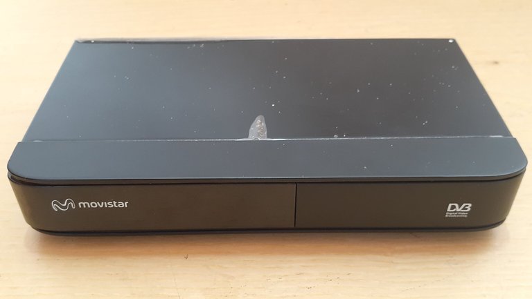 |  |  |
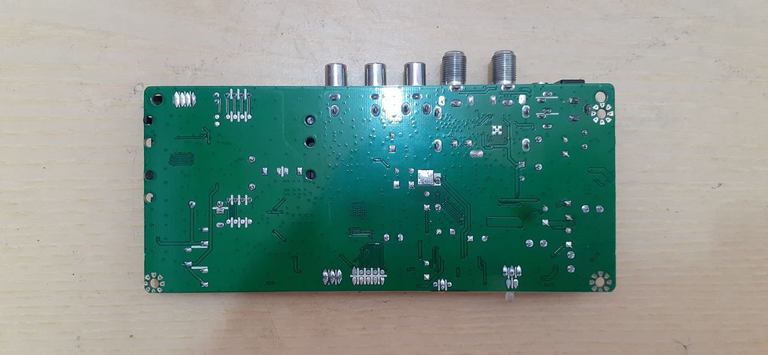
Como les mencione anteriormente voy a realizar la revisión y la reparación de un dispositivo de tv satelital, en este caso se trata de un decodificador de la marca Movistar. Lo primero que hago siempre es verificar el estado físico del dispositivo que me entregan para reparar, una vez pueda verificar su estado físico actual procedo a desarmarlo.
As I mentioned before, I am going to perform the review and repair of a satellite TV device, in this case it is a Movistar decoder. The first thing I always do is to verify the physical state of the device that I am given to repair, once I can verify its current physical state I proceed to disassemble it.
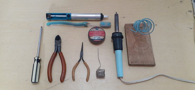 | 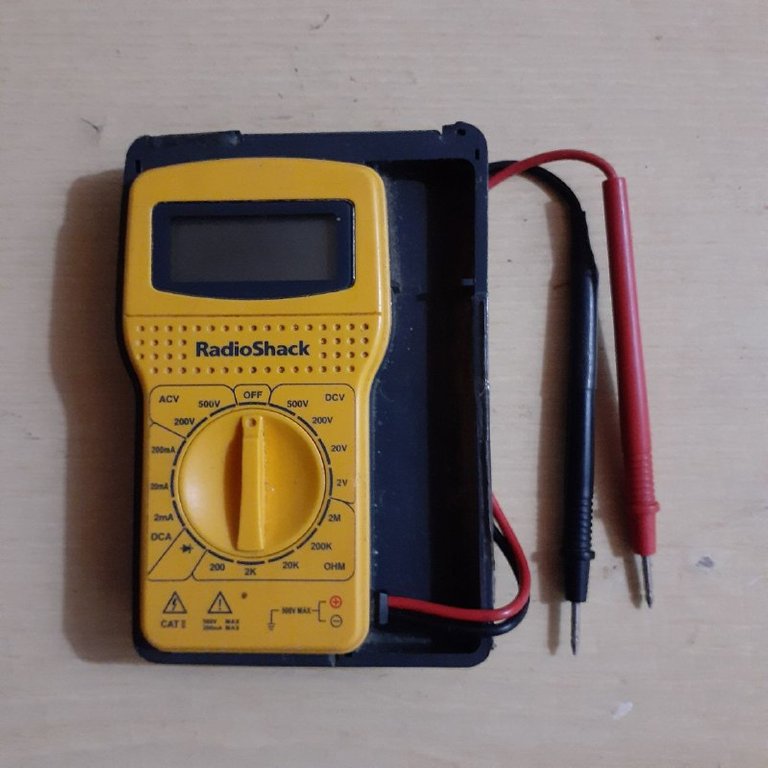 |
Antes de comenzar con el procedimiento específico de la reparación y seguir con la revisión, quiero comentarles de alguna de las herramientas que utilizo en mis reparaciones normalmente, en este caso podemos observar en las fotografías de arriba que haré uso de un destornillador de estrella, una pinza de corte, una pinza delgada, estaño 60/40, flux, un cautín, una base para el cautín, un extractor de estaño, un cepillo de dientes viejo y por supuesto hago uso de un multímetro.
Before starting with the specific procedure of the repair and continue with the revision, I want to tell you about some of the tools I normally use in my repairs, in this case we can see in the pictures above that I will use a Phillips screwdriver, a cutting pliers, a thin tweezers, tin 60/40, flux, a soldering iron, a base for the soldering iron, a tin extractor, an old toothbrush and of course I make use of a multimeter.
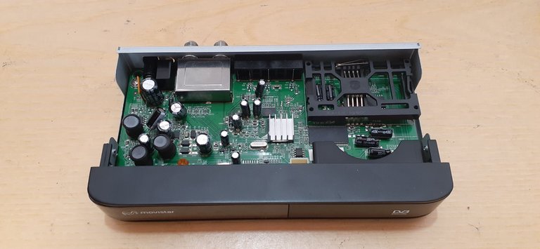 |  |  |
Entonces, una vez mencionadas las herramientas de las que hago uso cuando realizo una revisión o reparación, continuamos con el procedimiento de revisión. Lo primero que haremos es retirar la cubierta superior del dispositivo, una vez hecho esto podemos retirar la parte frontal la cual me dio un poco de trabajo, pero luego de intentarlo un rato pude retirarla y finalmente desprendemos la placa del chasis, como lo pueden ver en las fotografías de arriba.
So, having mentioned the tools I make use of when performing an overhaul or repair, let's continue with the overhaul procedure. The first thing we will do is remove the top cover of the device, once this is done we can remove the front part which gave me a little work, but after trying for a while I was able to remove it and finally we detach the chassis plate, as you can see in the pictures above.
 | 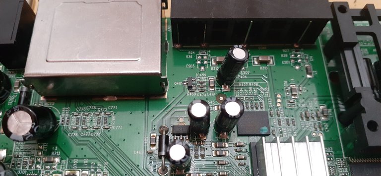 |  |
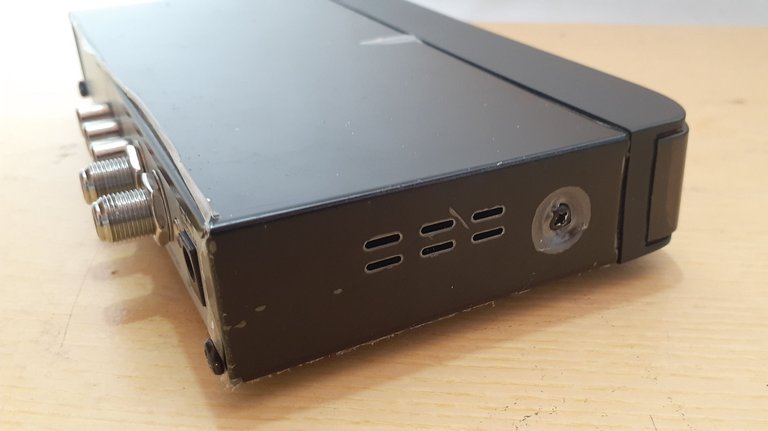
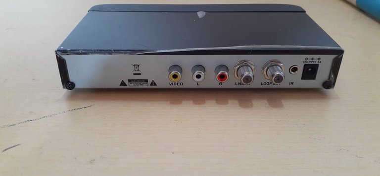
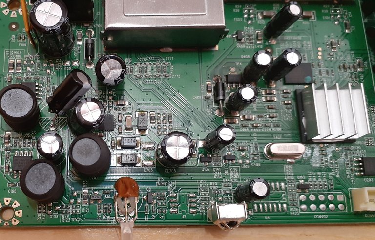
Una vez que tenemos la placa o el circuito fuera de su chasis, procedemos a realizar una inspección visual por la parte de arriba y por la parte de abajo. Lo que observaremos será el estado de las soldaduras, que no estén frías, que ninguna pista esté cortada o dañada y que no haya evidencia de restos de líquidos. Seguidamente realizaremos una inspección visual por la parte superior de la placa, donde es importante verificar el estado de los componentes, como por ejemplo los capacitores electrolíticos, de los cuales hay que verificar que no estén en mal estado, es decir, que no estén hinchados por arriba, rotos por debajo y tampoco que exista algún derrame de líquido de los mismos, quesería el líquido dieléctrico. También verificamos que no haya ningún corto y que ninguna pista superficial este dañada, verificamos también el estado de los puertos que tiene en la parte lateral, como son los conectores RCA, los coaxiales y el pin hembra donde el dispositivo recibe el voltaje. Es importante también verificar el estado del adaptador de voltaje para descartar en primera instancia que el mismo no esté averiado.
Once we have the board or the circuit out of its chassis, we proceed to perform a visual inspection from the top and the bottom. What we will observe will be the state of the soldering, that they are not cold, that no track is cut or damaged and that there is no evidence of liquid remains. Next we will make a visual inspection of the upper part of the board, where it is important to verify the condition of the components, such as the electrolytic capacitors, which must be verified that they are not in bad condition, i.e., that they are not swollen at the top, broken at the bottom and that there is no liquid spillage from them, which would be the dielectric liquid. We also verify that there is no short and that no surface track is damaged, we also check the condition of the ports you have on the side, such as RCA connectors, coaxial and female pin where the device receives the voltage, it is also important to check the status of the voltage adapter to rule out in the first instance that it is not broken.
 |  | 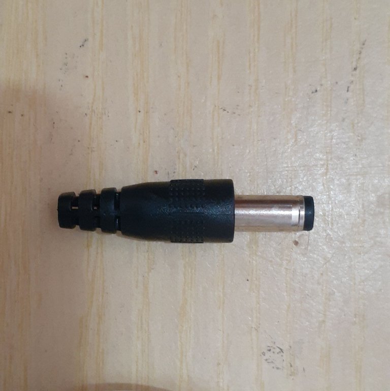 |
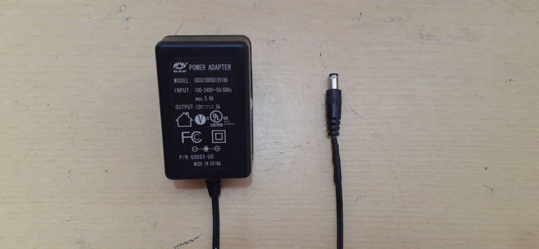
Habiendo realizado la inspección visual procederemos a realizar algunas pruebas con el multímetro, como por ejemplo conectar el adaptador de voltaje a un tomacorriente y verificar que el mismo tenga la salida el voltaje adecuada según las especificaciones del mismo. Cuando realicé la prueba del adaptador del dispositivo pude darme cuenta que este no tenía ningún voltaje en la salida, lo que me dio la sospecha de que podría estar averiado, resultando finalmente que la punta del mismo se encontraba en cortocircuito.
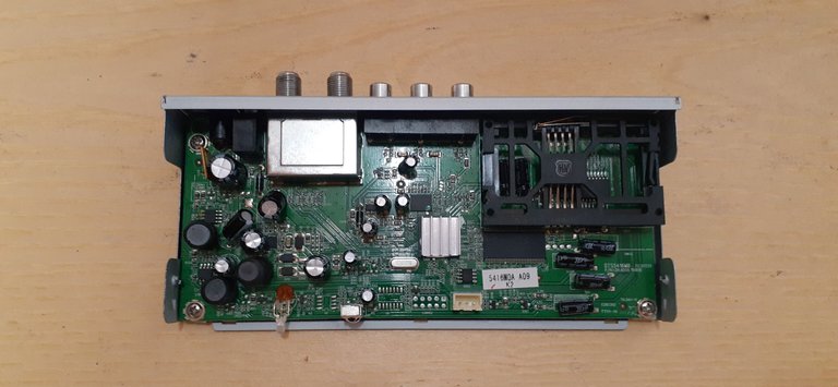
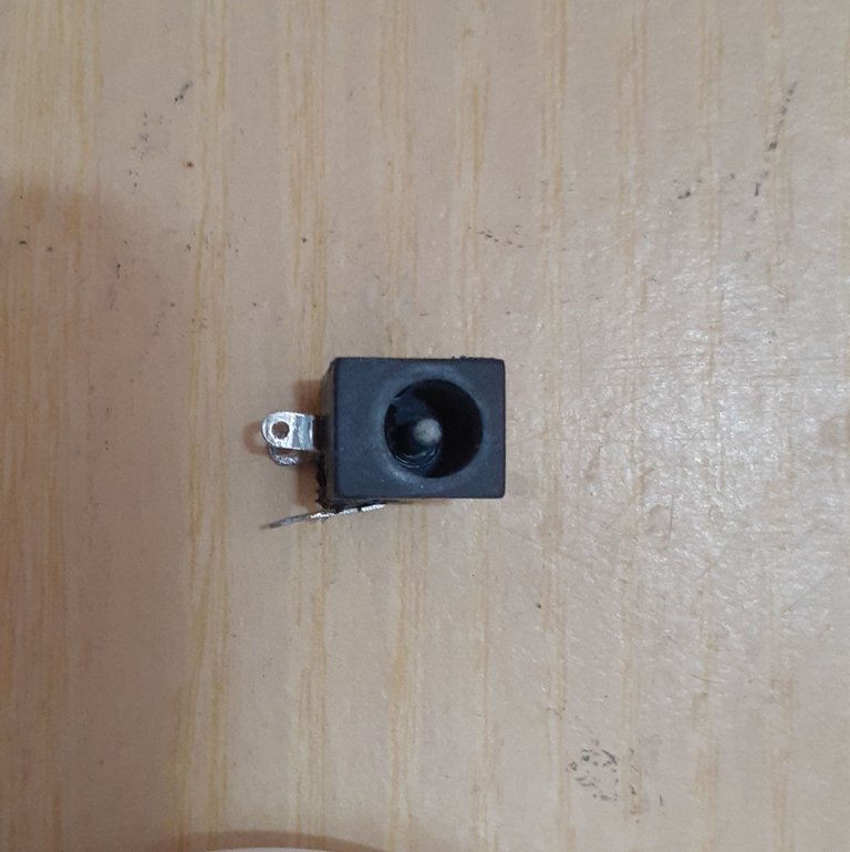
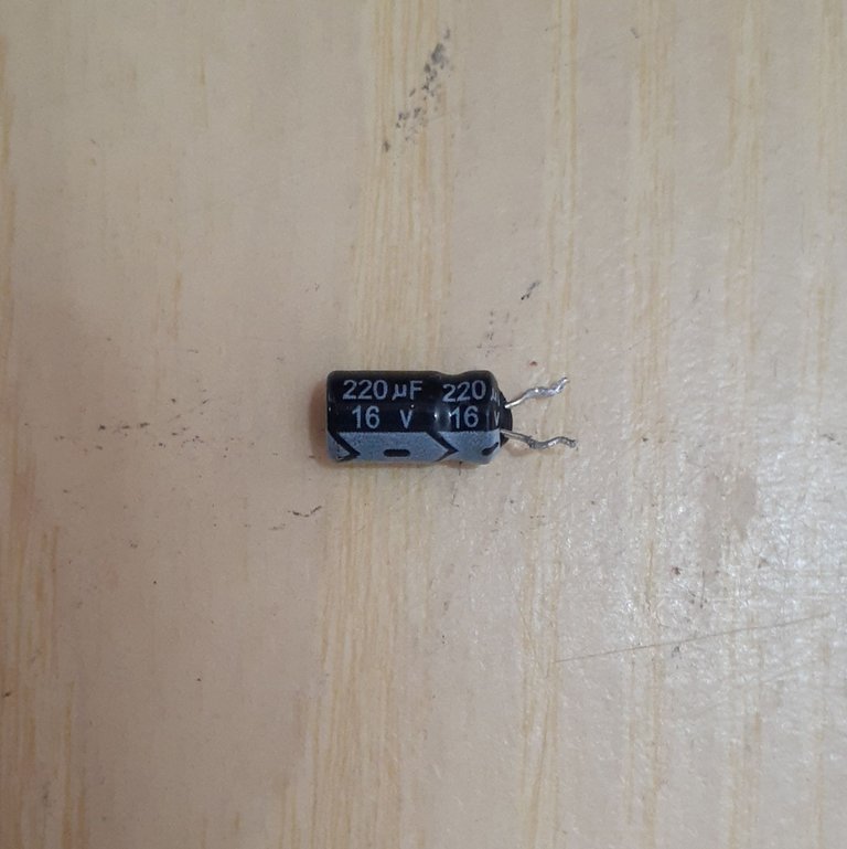
En la placa el año que encontramos estaba localizado en el pin hembra de la conexión de alimentación y un capacitor el cual se encontraba dañado ya que el sello de goma inferior estaba dañado, lo cual es un indicio de que el capacitor sufrió un exceso de voltaje.
En las fotografías de arriba pueden observar los daños encontrados, el pin de alimentación hembra se encuentra sulfatado y en cortocircuito, luego del capacitor electrolítico que les hablé antes, pueden observar cómo está dañado en la parte inferior y realizando unas pruebas con el multímetro me percaté que también estaba desvalorizado.
Y finalmente la punta del atador de voltaje tuvimos que cortarla para sustituirla ya que dicha punta estaba en cortocircuito.
Having made the visual inspection proceed to perform some tests with the multimeter, such as connecting the voltage adapter to a power outlet and verify that it has the proper voltage output according to its specifications. When I performed the test of the device adapter I could realize that this had no voltage at the output, which gave me the suspicion that it might be faulty, resulting finally that the tip of it was short-circuited.
On the board the year we found was located on the female pin of the power connection and a capacitor which was damaged since the lower rubber seal was damaged, which is an indication that the capacitor suffered an excess voltage.
In the pictures above you can see the damage found, the female power pin is sulfated and short-circuited, then the electrolytic capacitor that I spoke before, you can see how it is damaged at the bottom and performing some tests with the multimeter I realized that it was also devalued.
And finally the tip of the voltage tether we had to cut it to replace it because the tip was short-circuited.
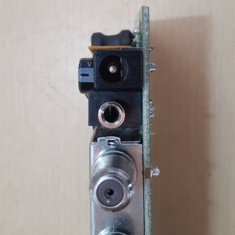 |  |
Luego de haber identificado los posibles daños. Procedemos a realizar la reparación. En este caso sustituimos el pin hembra de la conexión de alimentación eléctrica en la placa, como lo pueden ver la foto de arriba y también sustituimos el capacitor electrolítico que se encontraba añado en la placa, se puede observar que es el capacitor que sobresale un poco más de la placa que el resto y se encuentra un poco inclinado a la derecha.
Procedemos a conectar el dispositivo a la alimentación una vez sustituida la punta del atador de voltaje, realizamos una pequeña de verificación para saber si el equipo enciende, ya que la falla era que el dispositivo no encendía.
After having identified the possible damages. We proceed to make the repair. In this case we replaced the female pin of the power supply connection on the board, as you can see in the photo above and we also replaced the electrolytic capacitor that was added on the board, you can see that it is the capacitor that protrudes a little more from the board than the rest and is a little inclined to the right.
We proceed to connect the device to the power supply once replaced the tip of the voltage tether, we made a small check to see if the equipment turns on, since the fault was that the device did not turn on.
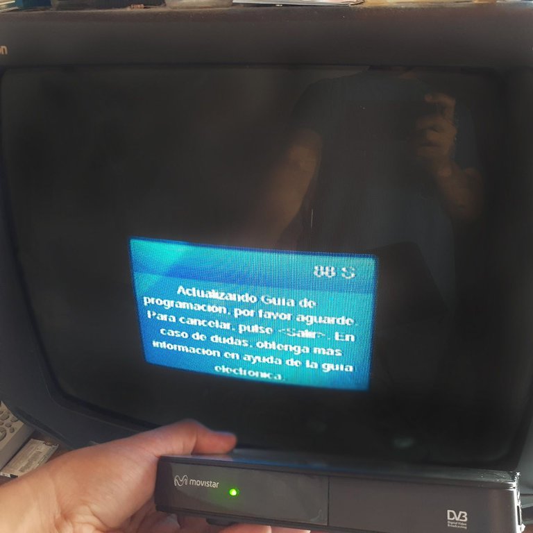 |  |
Y para terminar, realizamos una prueba completa del dispositivo conectándolo a un televisor para verificar que encendiera y que el mismo realizara su proceso de inicio normalmente, como lo pueden observar en la fotografía.
And to finish, we made a complete test of the device connecting it to a television to verify that it turned on and that the same one carried out its process of beginning normally, as you can observe it in the photography.

Hasta la siguiente publicación!
Until the next post!
Todas las fotografías fueron tomadas con mi celular SAMSUNG Galaxy A20.
All photographs were taken with my SAMSUNG Galaxy A20 cell phone.
El separador de texto y las demás imágenes son de mi autoría.
The text separator and other images are of my authorship.

https://twitter.com/robertsreinold/status/1480884780053024769
The rewards earned on this comment will go directly to the person sharing the post on Twitter as long as they are registered with @poshtoken. Sign up at https://hiveposh.com.
Que buena explicación das sobre esta reparación, muy interesante e listrativa tu publicación.