Discharge capacitors [Eng+Spa]
English

Greetings, it is a pleasure to share a new publication in this community. I hope they are as well as possible.
I keep working at times on the microwave that I was restoring in the previous repair post, as the expenses are on my own, I couldn't go faster.
I've come a long way, with the control board repair. But there are still more details to get the oven ready. The high voltages with which the equipment operates remind me that:
Do not handle this type of equipment if you do not have the training for it.
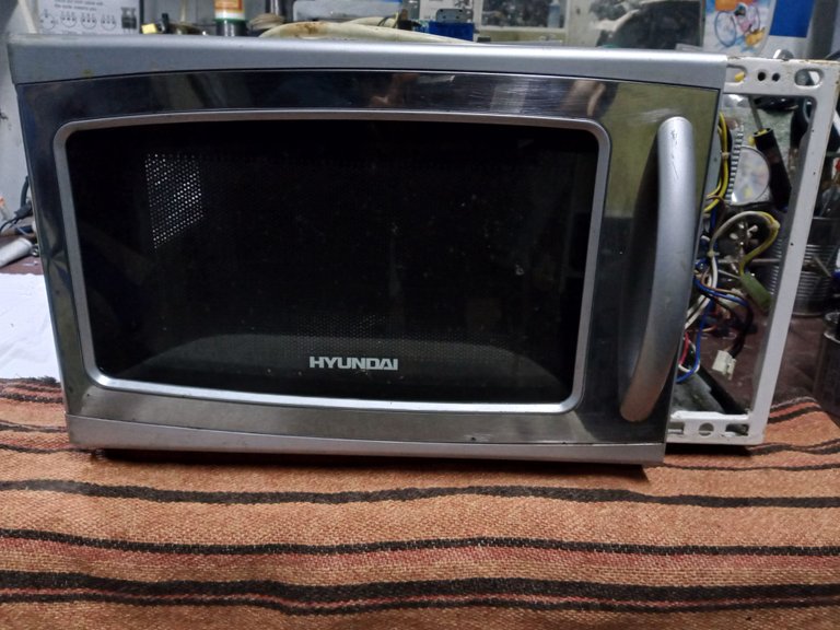
An important part of the electrical power system of this equipment requires the use of a capacitor in the high voltage zone, at the output of the transformer. I have to verify its good condition. Highlighted in the red circle.

You must not touch the terminals of a capacitor or you may receive a significant shock, and you may not use any device to measure whether the capacitor is still charged, which can destroy the tester being used.
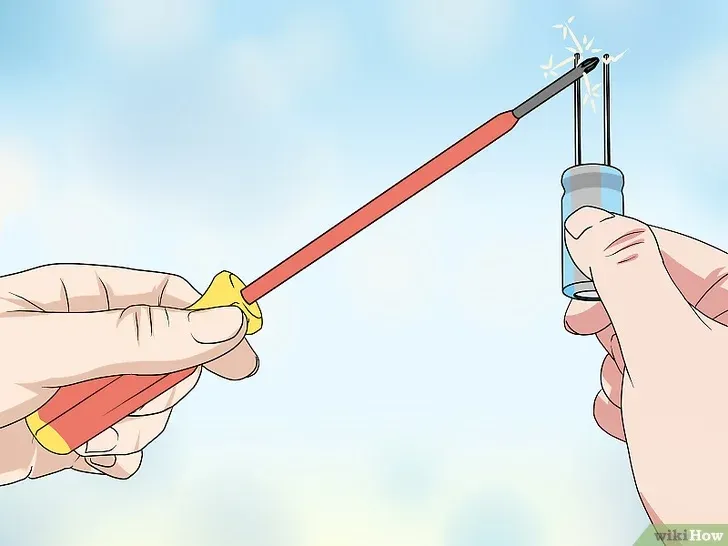
In the days of analog equipment, the technician used to make a short circuit between the two terminals of the capacitor to discharge, generate a spark and the capacitor was discharged. This is how they discharged the capacitors of: the washing machine, water pump, oven or the equipment they were checking.
Image's Source - Image Source
In these most current equipment, causing a spark by short-circuiting a capacitor, we can end up damaging the electronic card of the device we are working on, which will cause us problems to carry out the equipment, and of course problems for the client.
Others connected a soldering iron to the capacitor terminals, so it is well discharged, if done correctly and the soldering iron is in good condition, but you have no way of being sure that the process went well.
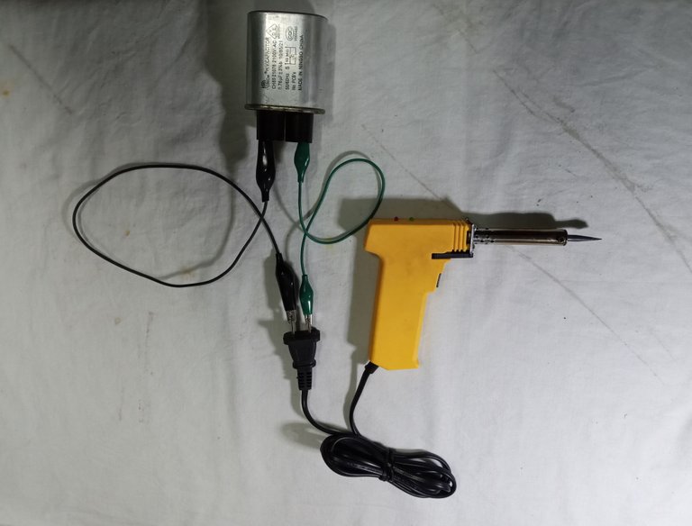
Some capacitors have a resistance between the terminals that is responsible for discharging when the power is cut off. But you don't have an indicator to show you if the resistor is good, and if you try to measure and it's charged, it will destroy the tester.

Image's Source - Fuente de la Imagen
So this is what the publication will be about, a very simple and useful device to discharge capacitors, which, as an addition to the homemade tool, can also act as a voltage detector for direct current from 2 Volts with a polarity indicator, and can detect current alternates from 30 volts to 110 volts.

A trusted site to make useful homemade tools, and to consult on the electronic subject that I always keep in mind is:

Comunidadelectronicos.com
So far, in everything I have needed, about electronics that is covered in this page, it has been a real help.
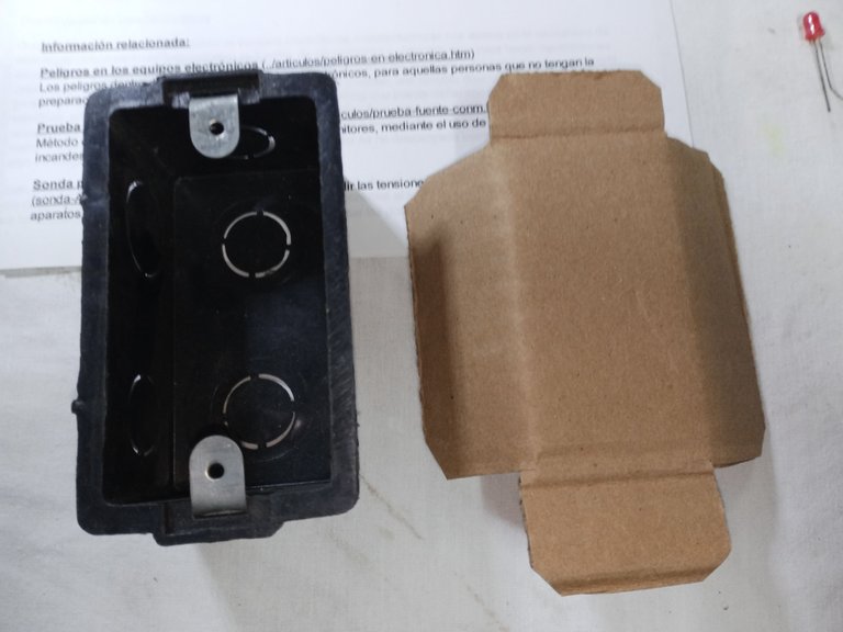
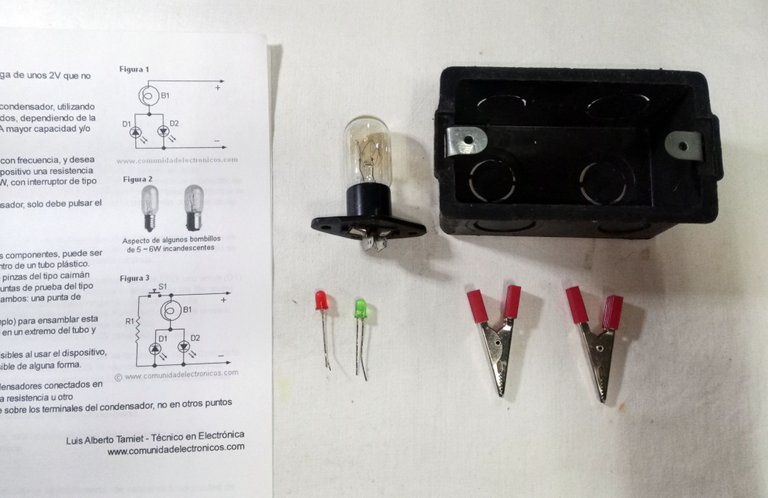
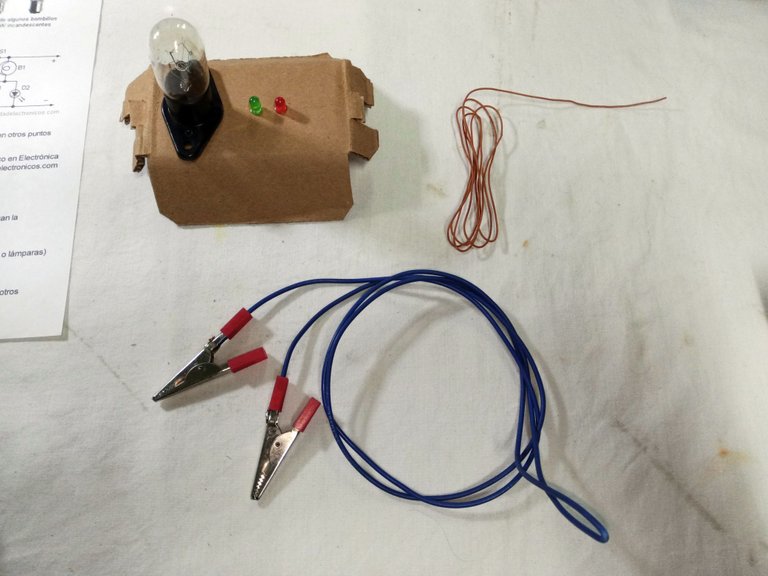
As always, I have used, for the most part, recycled components from discarded equipment: the lamp and its base are from a discarded microwave oven, the cable is recycled from a damaged refrigeration equipment, the tweezers for the tips and the leds used, I left over from a previous project.
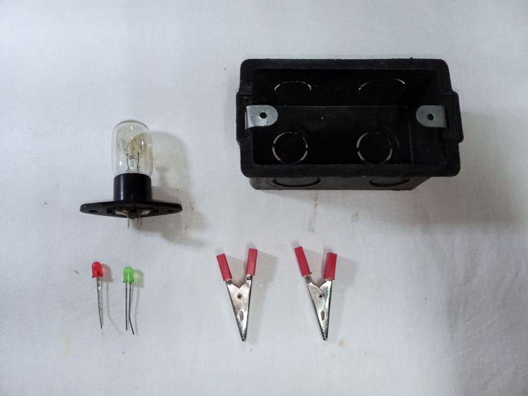
Use a 2 by 4 plastic box as the circuit box and cardboard to make the mounting bracket.
The assembly is really very simple: D1 is the green led, D2 the red led, B1 is the microwave bulb.


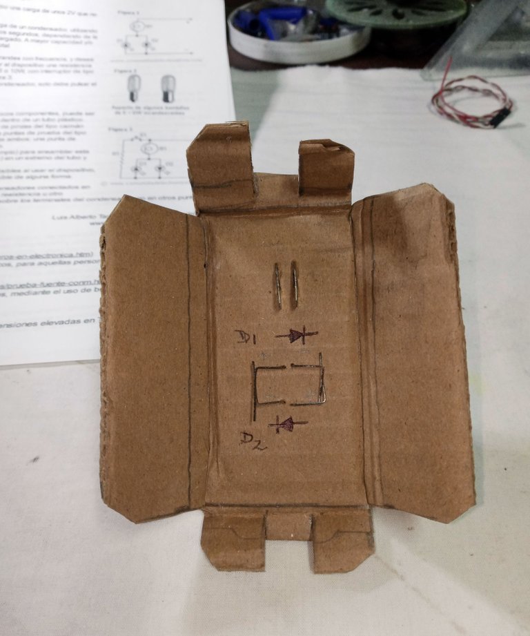

The resistor R1, of 4.7 K ohm, is optional, but when I built and tested the circuit without placing the resistor, the red led ended up being damaged.
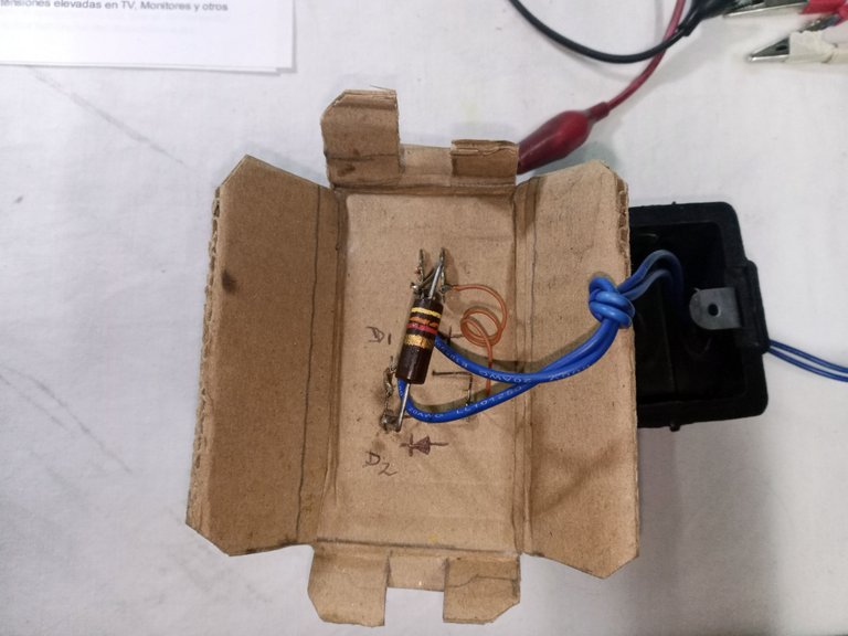
It does not have much science, to discharge the capacitor: just connect a clamp at each end until the led turns off, at that moment in theory there should be less than 2 Volts left in the capacitor, which is low enough to be able to handle it without risk for the technician or for the equipment being intervened.
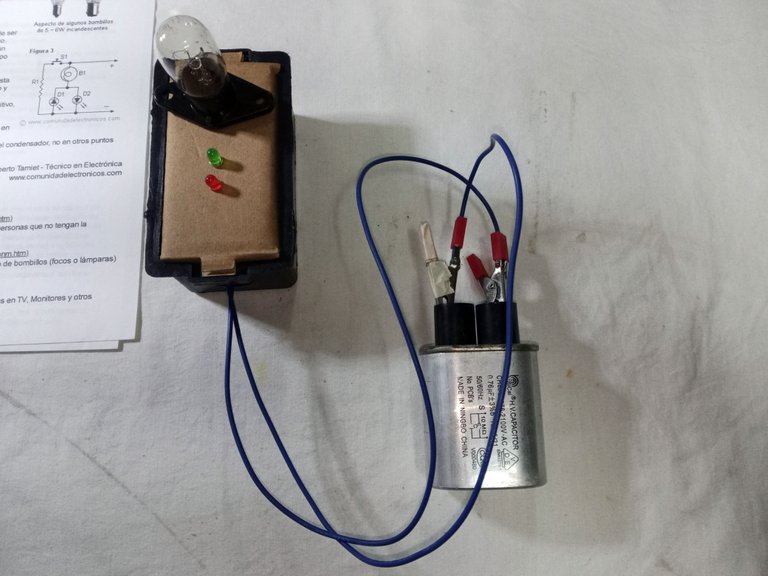
I won't be using it as a voltage detector, usually when checking voltages I need to know precisely the present value. But it is useful for discharging capacitors safely and more professionally in: voltage sources, air conditioners, washing machines. And the other equipment that arrives at the workshop.
Well, I hope that at some point it can be useful to you. And please remember:
Do not intervene electrical equipment, without being trained to do so
Thank you very much for stopping by and reading.
Have a great day.
Peace.

The banner was edited in Canvas.
I have used Google translate for the English language.
Images unless stated are images taken in my workshop.
Español
Saludos, es un placer compartir una nueva publicación en esta comunidad. Espero que estén lo mejor posible.
Sigo trabajando por ratos en el microondas que estaba restaurando en la publicación anterior de reparaciones, como los gastos van por mi cuenta, no he podido ir más deprisa.
He adelantado mucho, con la reparación de la tarjeta de control. Pero quedan aún más detalles para dejar el horno listo. Las altas tensiones con las que opera el equipo, me hacen recordarles que:
No manipulen este tipo de equipos si no tiene la capacitación para ello.
Una parte importante del sistema de fuerza eléctrica de este equipo requiere del uso de un capacitor en la zona del alto voltaje, a la salida del transformador. Tengo que verificar su buen estado. Resaltado en el círculo rojo.
No se debe tocar los terminales de un capacitor o se puede recibir una descarga importante, y tampoco puede usar ningún dispositivo para medir, si el capacitor aún está cargado, lo que puede destruir el probador o tester que se esté usando.
En los tiempos de equipos analógicos, el técnico solía hacer cortocircuito entre los dos terminales del capacitor para hacer la descarga, generaba un chispazo y se daba por descargado el capacitor. Así descargaban los capacitores de: la lavadora, bomba de agua, horno o del equipo que estaban revisando.
Image's Source - Fuente de la Imagen
En estos equipos más actuales, provocar un chispazo al cortocircuitar un condensador, podemos terminar por dañar la tarjeta electrónica del artefacto que estemos trabajando, lo que nos causara problemas para sacar adelante el equipo, y por supuesto problemas para el cliente.
Otros conectaban un cautín de soldar a los terminales del capacitor, así queda bien descargado, si se hace de forma correcta y el cautín está en buenas condiciones, pero no tienes manera de estar seguro de que el proceso ha ido bien.
Algunos capacitores traen una resistencia entre los terminales que se encarga de hacer la descarga cuando se corta la energía. Pero no tienes un indicador que te muestre si la resistencia está en buen estado, y si tratas de medir y está cargado, destruirá el tester.
Image's Source - Fuente de la Imagen
Así que de esto irá la publicación, un muy sencillo y útil dispositivo para descargar los capacitores, que como agregado la herramienta casera también puede hacer de detector de voltaje de corriente continua a partir de 2 Volts con indicador de polaridad, y que puede detectar corriente alterna desde los 30 Volts a los 110 Volts.
Un sitio de confianza para hacer útiles herramientas caseras, y consultar sobre el tema electrónico al que siempre tengo en cuenta es:
Comunidadelectronicos.com
Hasta ahora, en todo lo que he necesitado, sobre electrónica que se trata en esta página, ha sido de real ayuda.
Como siempre, he usado, en mayor parte, componentes reciclados de equipos descartados: la lámpara y su base es de un horno microondas descartado, el cable es reciclado de un equipo de refrigeración dañado, las pinzas para las puntas y los leds empleados, me quedaron de un proyecto anterior.
Use un cajetín plástico de 2 por 4 como caja del circuito y cartón para hacer el soporte del montaje.
El montaje realmente es muy simple: D1 es el led verde, D2 el led rojo, B1 es la bombilla de microondas.
La resistencia R1, de 4,7 K ohm, es opcional, pero cuando arme y probé el circuito sin colocar la resistencia, el led rojo termino dañándose.
No tiene mayor ciencia, para descargar el capacitor: solo se conecta una pinza en cada extremo hasta que el led se apague, en ese momento en teoría debería quedar menos de 2 Volts en el capacitor, que es lo suficientemente bajo para poder manipularlo sin riesgo para el técnico ni para el equipo que se esté interviniendo.
No lo usaré como detector de voltaje, por lo general cuando reviso voltajes necesito saber con precisión el valor presente. Pero si me es útil para descargar de forma segura y más profesional los capacitores en: fuentes de voltajes, aires acondicionados, lavadoras. Y los demás equipos que me lleguen al taller.
Bueno, espero que en algún momento les pueda a ser útil. Y por favor recuerden:
No deben intervenir equipos sin estar lo suficientemente capacitados.
Muchas gracias por pasar y leerme.
Que tengan un excelente día.
Paz.
El banner fue editado en Canvas.
He usado el traductor de Google para el idioma inglés.
Las imágenes a menos que se indiquen son imágenes tomadas en mi taller.
https://twitter.com/2165453306/status/1631485660170207232
The rewards earned on this comment will go directly to the people( @pedrobrito2004 ) sharing the post on Twitter as long as they are registered with @poshtoken. Sign up at https://hiveposh.com.
This post has been manually curated by @bhattg from Indiaunited community. Join us on our Discord Server.
Do you know that you can earn a passive income by delegating to @indiaunited. We share more than 100 % of the curation rewards with the delegators in the form of IUC tokens. HP delegators and IUC token holders also get upto 20% additional vote weight.
Here are some handy links for delegations: 100HP, 250HP, 500HP, 1000HP.
100% of the rewards from this comment goes to the curator for their manual curation efforts. Please encourage the curator @bhattg by upvoting this comment and support the community by voting the posts made by @indiaunited.
Very appreciated your support. Have an excellent end of the week.
This is really a great project I long being searching to learn. But it is such kinda complex physics even though I know how some of these electronics function.
So if I may ask, when you tested the circuit without placing the resistor and the red led damaged so what was the opposite results. Did you continue to test for discharging of the capacitor?
What was the function of the bulb? I didn't see that light was emitted after the completion of the discharging of the capacitor.
The idea of the tool is that the capacitor's electricity is consumed by the bulb filament.
It can take a maximum of two seconds or less, so that it is downloaded, so taking out the image of the exact moment did not become easy, I was unfocused. I am alone in the workshop.
When the voltage falls below the two volts, no LED or lamp should be turned on.
Resistance is supposed to be optional for voltage discharge to work even faster. In the first assembly that I did the tests, without adding the resistance, it worked, but the red LED ended damaged.
So choose to place the resistance, change the damaged LED and since then, it works without damaging any LED.
Thank you very much for reading and leaving your comment.
Justo hace unos días había visto un aparato similar en un Reel de Instagram, es de gran utilidad para mantenerse seguro y esta bueno que menciones que no toquen estos equipos sin el debido conocimiento, un microondas mal manipulado puede ser muy peligroso.
Si es que en algunos artefactos es mayor el riesgo de sufrir lesiones. Por eso siempre se hace la salvedad, un mal manejo puede resultar en un mal mayor.
Gracias por pasar amigo.